
Liquid crystal display device

A liquid crystal display device, thin film transistor technology, applied in static indicators, nonlinear optics, optics, etc., can solve problems such as increased cost, increased manufacturing process and circuit complexity, high voltage range of data drivers, etc. The effect of reduction and cost reduction

Inactive Publication Date: 2011-06-01
INNOCOM TECH (SHENZHEN) CO LTD +1
View PDF0 Cites 21 Cited by
  • Summary
  • Abstract
  • Description
  • Claims
  • Application Information

AI Technical Summary

Problems solved by technology

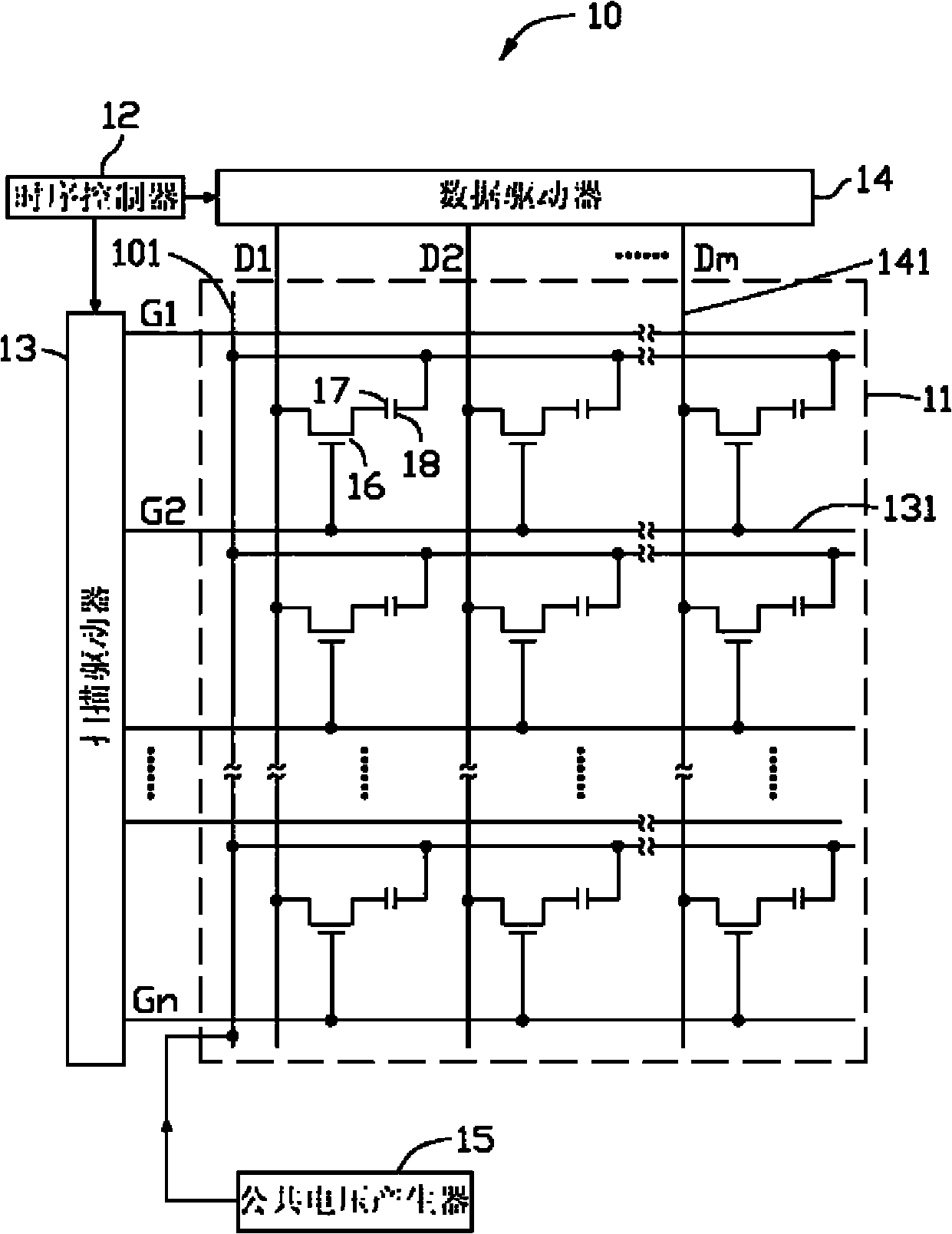
Because the common voltage generator 15 produces a fixed common voltage, the highest voltage of the pixel electrode 17 needs to reach more than twice the voltage of the common electrode 18, and the voltage of the pixel electrode 17 is provided from the data driver 14, so the data driver 14 provides The operating voltage range is more than twice that of the public voltage. This method undoubtedly requires a high voltage range for the data driver 14, and the complexity of the manufacturing process and the circuit is relatively increased, and the cost will also be increased accordingly.

Method used


Image

  • Liquid crystal display device
  • Liquid crystal display device
  • Liquid crystal display device

Examples


Embodiment Construction

[0018] see figure 2 , image 3 and Figure 4 The liquid crystal display device 20 of the first embodiment of the present invention includes a liquid crystal panel 21 , a timing controller 22 , a scan driver 23 , a data driver 24 , a first common voltage generator 25 and a second common voltage generator 26 .

[0019] Scan driver 23 and data driver 24 are used for driving liquid crystal panel 21, timing controller 22 is used for controlling scan driver 23 and data driver 24, and first common voltage generator 25 and second common voltage generator 26 are used for liquid crystal panel 21 Provides common voltage.

[0020] The liquid crystal panel 21 is provided with a plurality of parallel scanning lines 232, a plurality of data lines 241 parallel to and perpendicular to the scanning lines 232, a first common line 251, a second common line 261, and a plurality of data lines 240 and scanning lines. 232 divides and defines the pixel units 27 distributed in a matrix.

[0021] E...


PUM


Abstract

The invention provides a liquid crystal display device. In the liquid crystal display device, a first public voltage and a second public voltage which are constantly changed are used, public electrodes of different pixel units at the same row are respectively connected with the first public voltage and the second public voltage, thus a data driver dose not need to provide twice public voltage, thereby relatively reducing the production process and circuit complexity of the driving circuit of the liquid crystal display device so as to reduce cost.

Description

technical field [0001] The invention relates to a liquid crystal display device. Background technique [0002] Liquid crystal displays are widely used because of their low radiation, light, thin and small size, and low power consumption. With the maturity and innovation of related technologies, there are more and more types. [0003] see figure 1 , the liquid crystal display 10 in the prior art includes a liquid crystal panel 11 , a timing controller 12 , a scan driver 13 , a data driver 14 and a common voltage generator 15 . The scan driver 13 and the data driver 14 are used to drive the liquid crystal panel 11 , the timing controller 12 is used to drive the scan driver 13 and the data driver 14 , and the common voltage generator 15 is used to provide a common voltage for the liquid crystal panel 11 . [0004] The liquid crystal panel 11 includes a plurality of parallel scan lines 131, a plurality of parallel and intersecting data lines 141 perpendicular to the scan lines...

Claims


Application Information

Patent Timeline
Patent Type & Authority Applications(China)
IPC IPC(8): G02F1/133G09G3/36
CPCG09G2320/0204G09G3/36G02F1/133G09G3/3614G09G3/3655
Inventor 陈育昇林育正洪文明林萤聪陈鹊如
Owner INNOCOM TECH (SHENZHEN) CO LTD
Learn More