Endoscope insertion shape analyzing system
An analysis system and endoscope technology, applied to the field of endoscope insertion shape analysis system and in vivo observation system, can solve problems such as different senses of incongruity
- Summary
- Abstract
- Description
- Claims
- Application Information
AI Technical Summary
Problems solved by technology
Method used
Image
Examples
no. 1 Embodiment approach
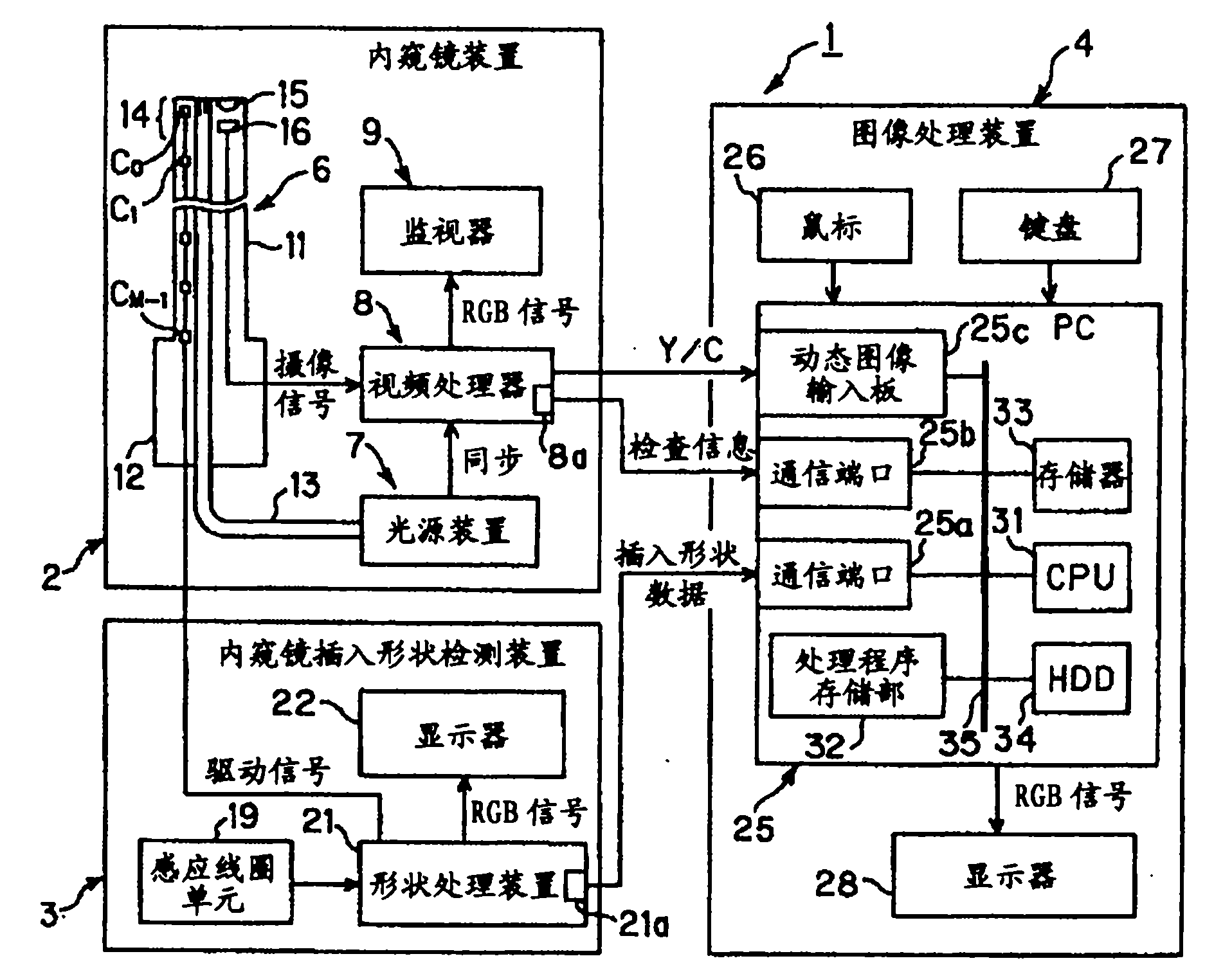
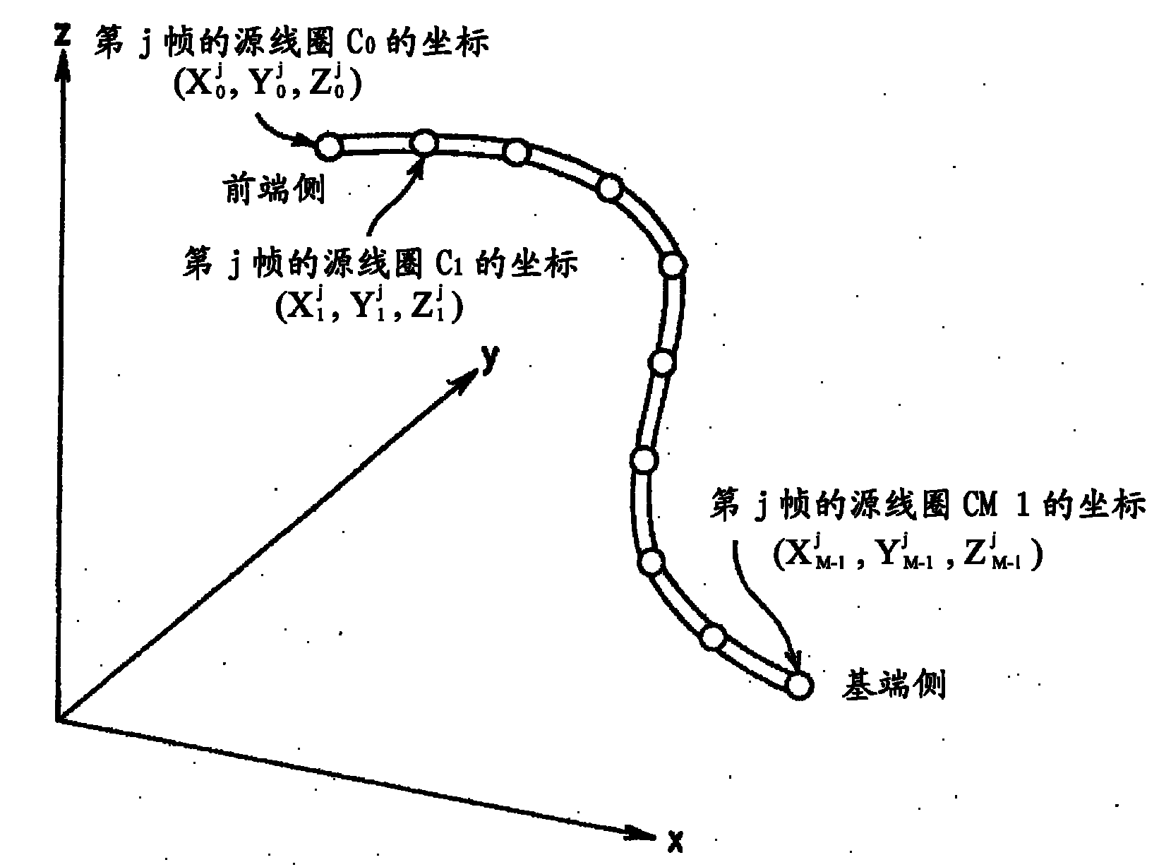
[0034] Figure 1 to Figure 5 It relates to the first embodiment of the present invention. figure 1 It is a figure which shows an example of the main part structure of the living body observation system concerning embodiment of this invention. figure 2 is shown in figure 1 Detected in the endoscope insertion shape detection device, set in figure 1 A diagram of the coordinates of the source coil on the insertion portion of the endoscope. Figure 3A is shown in figure 1 A diagram showing an overview of insertion shape data generated by the endoscope insertion shape detection device. Figure 3B is showing Figure 3A A diagram of a summary of the data and information contained within the parties of the frame data. Figure 3C is showing Figure 3B A diagram showing the outline of the three-dimensional coordinate data included in the coil coordinate data. Figure 4 It is a flowchart showing an example of processing performed when determining the presence or absence of a ring...
no. 2 Embodiment approach
[0084] Figure 6 to Figure 10 It relates to the second embodiment of the present invention. Image 6 It is a flowchart showing an example of processing performed when detecting an insertion stop point in the second embodiment of the present invention. and, Figure 7 is to show that in the second embodiment of the present invention, the evaluation passes Image 6 A flow chart of an example of processing performed when a series of processing detects an insertion stop point. Figure 8 is shown based on Figure 7 A diagram of an example of the processing results of a series of processing displayed on the display with the first mark. Figure 9 is shown based on Figure 7 A diagram of an example of the processing results of a series of processing displayed on the display with the second mark. Figure 10 is to show that in the second embodiment of the present invention, the evaluation passes Image 6 A sequence of processing that is performed when an insertion stop point is de...
no. 3 Embodiment approach
[0127] Figure 11 to Figure 12 It relates to the third embodiment of the present invention. Figure 11 is shown by figure 1 A diagram of the configuration of functional blocks realized by the image processing device. Figure 12 is shown in the third embodiment of the present invention, by having Figure 11 An explanatory diagram of the processing flow performed by each block of the shown configuration.
[0128] In addition, the living body observation system of the third embodiment has substantially the same configuration as the living body observation system 1 described in the first embodiment and the second embodiment. Therefore, in this embodiment, the description of parts having the same configuration or function as those of the living body observation system 1 of the first and second embodiments will be omitted, and the description will be mainly made about the parts having the same structure and function as those of the first and second embodiments. Description of di...
PUM
 Abstract
Description
Claims
Application Information
 - R&D
- Intellectual Property
- Life Sciences
- Materials
- Tech Scout
- Unparalleled Data Quality
- Higher Quality Content
- 60% Fewer Hallucinations
Browse by: Latest US Patents, China's latest patents, Technical Efficacy Thesaurus, Application Domain, Technology Topic, Popular Technical Reports.
© 2025 PatSnap. All rights reserved.Legal|Privacy policy|Modern Slavery Act Transparency Statement|Sitemap|About US| Contact US: help@patsnap.com


