Image processing device for vehicle
An image processing device and vehicle technology, applied in image data processing, image data processing, image communication, etc., can solve problems such as deviation near the boundary, achieve smooth connection, and realize the effect of incongruity
- Summary
- Abstract
- Description
- Claims
- Application Information
AI Technical Summary
Problems solved by technology
Method used
Image
Examples
no. 1 approach
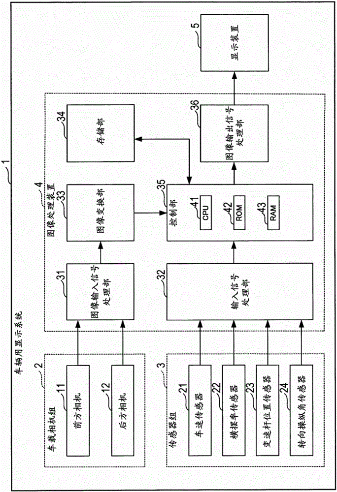
[0028] The following is attached Figure 1 The first embodiment of the present disclosure will be described first.
[0029] The vehicle display system 1 of the present embodiment is mounted on a vehicle, such as figure 1 As shown, a vehicle-mounted camera group 2 , a sensor group 3 , an image processing device 4 , and a display device 5 are provided. The image processing device 4 is a vehicle image processing device in the present disclosure.
[0030] The vehicle-mounted camera group 2 is composed of a front camera 11 and a rear camera 12 . The front camera 11 is mounted on the front side of a vehicle (hereinafter referred to as the own vehicle) on which the vehicle display system 1 is mounted, and repeatedly captures images of the ground in front of the own vehicle. The rear camera 12 is installed on the rear side of the own vehicle, and repeatedly photographs the ground surface behind the own vehicle.
[0031] The sensor group 3 is composed of a vehicle speed sensor 21 ,...
no. 2 approach
[0086] below, with Figure 1 First, the second embodiment of the present disclosure will be described. However, in the second embodiment, the parts different from the first embodiment will be described.
[0087] The vehicle display system 1 of the second embodiment is the same as the first embodiment except that the tire parameter update process is changed.
[0088] The tire parameter update process of the second embodiment is the same as the first embodiment except that the processes of S270 to S290 and S320 to S360 are omitted and the processes of S410 to S490 are added.
[0089] That is, if Figure 7 As shown, when the measurement object is detected (S260: YES), in S410, the moving distance and moving direction of the host vehicle are calculated in the same manner as in S80. Then, in S420, the front top image stored in the storage unit 34 is used to create a position comparison image representing the rear display region R2 and the middle display region R3, and the create...
no. 3 approach
[0102] The following is attached Figure 1 A third embodiment of the present disclosure will be described first. However, in the third embodiment, the parts different from the first embodiment will be described.
[0103] The vehicle display system 1 of the third embodiment is the same as that of the first embodiment except that the tire parameter update process is changed.
[0104] The tire parameter update process of the third embodiment is a process that is repeatedly executed at a preset execution cycle during the operation of the image processing device 4 .
[0105] When this tire parameter update process is executed, the control unit 35 will Figure 9 As shown, firstly, in S610, it is judged whether the preset processing start condition is satisfied. The processing start condition of this embodiment is that the tire parameter update button provided in the vehicle compartment is pressed.
[0106] Here, when the processing start condition is not satisfied (S610: NO), th...
PUM
 Abstract
Description
Claims
Application Information
 - R&D
- Intellectual Property
- Life Sciences
- Materials
- Tech Scout
- Unparalleled Data Quality
- Higher Quality Content
- 60% Fewer Hallucinations
Browse by: Latest US Patents, China's latest patents, Technical Efficacy Thesaurus, Application Domain, Technology Topic, Popular Technical Reports.
© 2025 PatSnap. All rights reserved.Legal|Privacy policy|Modern Slavery Act Transparency Statement|Sitemap|About US| Contact US: help@patsnap.com


