
Clock adjustment circuit and adjustment method for clock circuit

A clock adjustment and circuit adjustment technology, applied in the field of microelectronics, can solve the problems of increasing phase error, charge and discharge current mismatch, etc., to improve the speed of adjustment, improve accuracy, reduce phase error and control voltage ripple the effect of

Inactive Publication Date: 2011-05-25
XIDIAN UNIV
View PDF4 Cites 34 Cited by
  • Summary
  • Abstract
  • Description
  • Claims
  • Application Information

AI Technical Summary

Problems solved by technology

[0005] Aiming at the problem of periodic ripple in the control voltage due to the switching delay of the charge pump in the related technology, and the shortcomings of charge and discharge current mismatch, charge injection and charge sharing, etc., will further increase the phase error and the ripple of the control voltage , the present invention proposes a clock adjustment circuit and an adjustment method for the clock circuit

Method used


Image

  • Clock adjustment circuit and adjustment method for clock circuit
  • Clock adjustment circuit and adjustment method for clock circuit
  • Clock adjustment circuit and adjustment method for clock circuit

Examples


Embodiment Construction

[0050] In order to make the object, technical solution and advantages of the present invention clearer, the present invention will be further described in detail below in conjunction with the accompanying drawings and specific embodiments. It should be understood that the specific embodiments described here are only used to explain the present invention, not to limit the present invention.

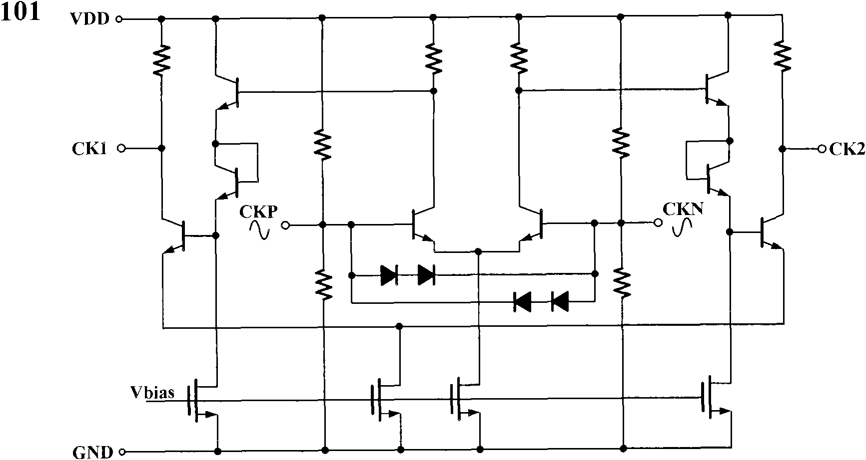
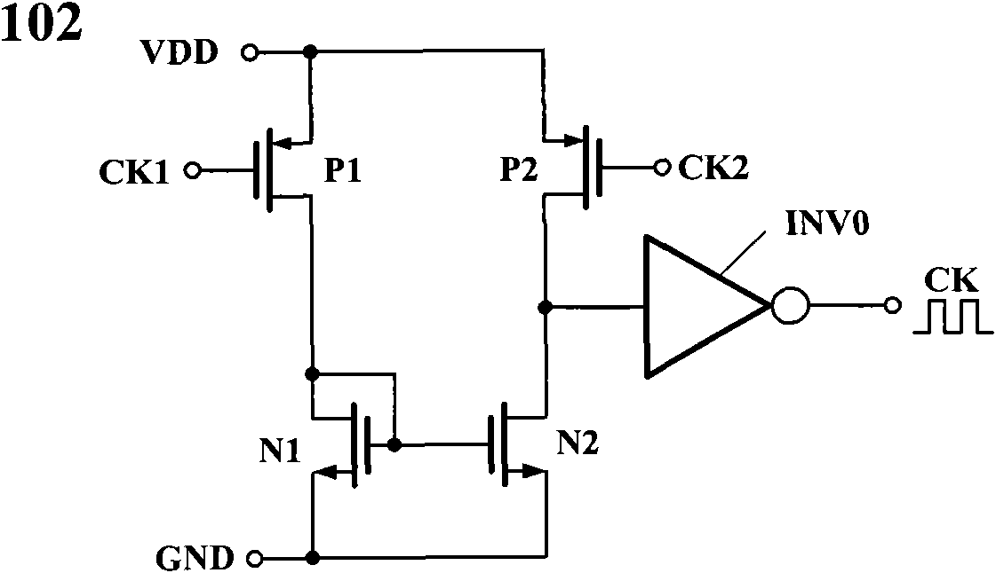
[0051] figure 1 is a structural block diagram of a clock adjustment circuit according to an embodiment of the present invention, such as figure 1 As shown, the duty cycle adjustment circuit includes:

[0052] A clock buffer amplifier 10 is used to receive an external differential clock signal, reshape the differential clock signal into a single-ended square wave clock signal, and output the single-ended square wave clock signal;

[0053] The phase detector 20 is used to receive the single-ended square wave clock signal from the clock buffer amplifier and the feedback signal from the duty r...


PUM


Abstract

The invention provides a clock adjustment circuit and an adjustment method for a clock circuit. The clock adjustment circuit comprises a clock buffer amplifier, a phase discriminator and a duty cycle adjustment circuit, wherein the clock buffer amplifier is used for receiving an external differential clock signal, shaping the differential clock signal into a single-end square wave clock signal and outputting the single-end square wave clock signal; the phase discriminator is used for receiving the single-end square wave clock signal from the clock buffer amplifier and a feedback signal from the duty cycle adjustment circuit, comparing the phase of the single-end square wave clock signal with the phase of the feedback signal to acquire a phase difference, and outputting the phase difference; and the duty cycle adjustment circuit is used for adjusting the duty cycle of the feedback signal by using the phase difference to acquire an adjusted feedback signal. The differential signal is shaped into the single-end square wave clock signal, the single-end square wave clock signal is compared with the feedback signal to acquire the phase difference, and the duty cycle is adjusted according to the phase difference, so that the complexity of duty cycle adjustment and hardware implementation can be effectively reduced, phase errors and the ripple waves of control voltage can be reduced, and adjustment accuracy is improved.

Description

technical field [0001] The invention belongs to the field of microelectronics, in particular to a clock adjustment circuit and an adjustment method for the clock circuit, which are used for high-speed and high-precision pipeline analog-to-digital converters. Background technique [0002] With the development of modern communication technology, high-speed and high-precision analog-to-digital converters are widely used, especially in military data communication systems and data acquisition systems. The demand for high-speed, high-resolution analog-to-digital converters is constantly increasing. In high-speed analog-to-digital converters, the timing error of the sampling clock often limits the maximum rate of a digital I / O interface, and at the same time increases the bit error rate of the communication link, limits the dynamic range of the analog-to-digital converter, and reduces its The signal-to-noise ratio directly affects the accuracy of the analog-to-digital converter. G...

Claims


Application Information

Patent Timeline
Patent Type & Authority Applications(China)
IPC IPC(8): H03K5/19
Inventor 刘帘曦彭增欣赵磊杨银堂丁瑞雪
Owner XIDIAN UNIV
Learn More