Compensation control circuit beneficial to harmonic reduction of active flyback power factor correction device

A power factor correction and compensation control technology, applied in the direction of output power conversion devices, electrical components, etc., can solve problems such as input current distortion, and achieve the effect of reducing low-order harmonics and improving the distortion at the peak of the input current.

Active Publication Date: 2011-05-25
ZHEJIANG UNIV
View PDF5 Cites 15 Cited by
  • Summary
  • Abstract
  • Description
  • Claims
  • Application Information

AI Technical Summary

Problems solved by technology

[0006] The technical problem to be solved by the present invention is to provide a new compensation control method and its circuit, aiming to solve t...

Method used


Image

  • Compensation control circuit beneficial to harmonic reduction of active flyback power factor correction device
  • Compensation control circuit beneficial to harmonic reduction of active flyback power factor correction device
  • Compensation control circuit beneficial to harmonic reduction of active flyback power factor correction device

Examples


Embodiment Construction

[0022] The present invention will be further described below in conjunction with the accompanying drawings and embodiments.

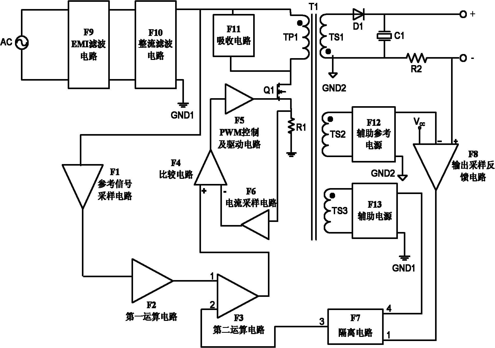
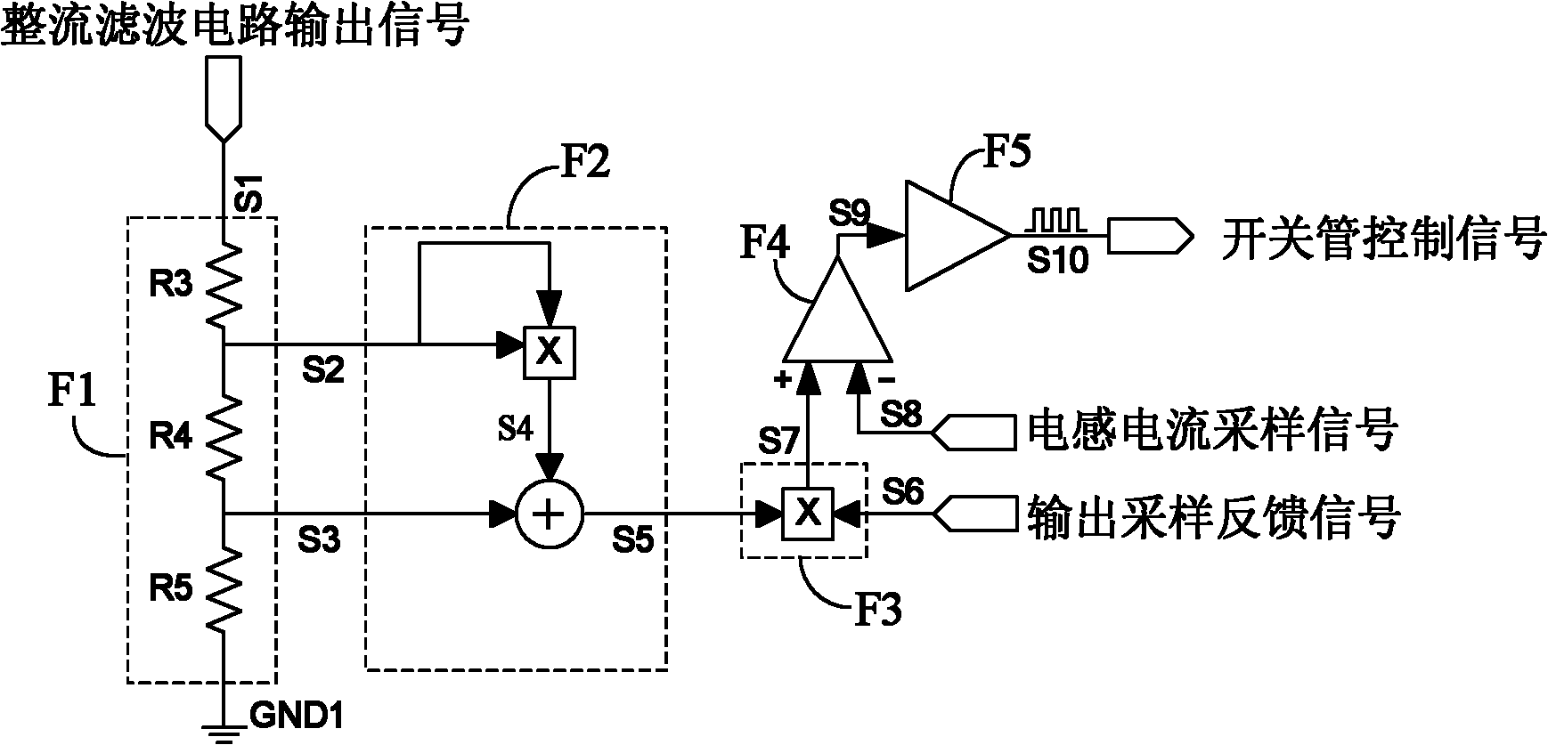
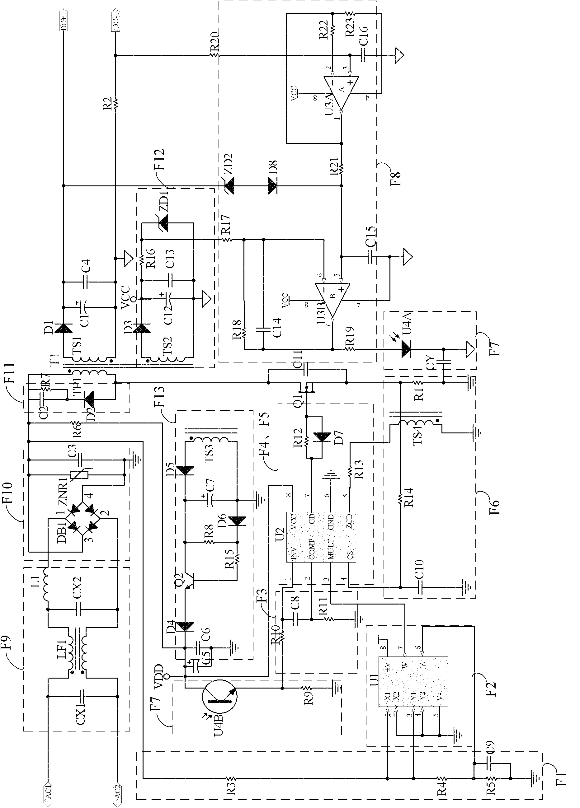
[0023] refer to figure 1 , a compensation control circuit that is beneficial to the harmonic reduction of active flyback power factor correction devices. The flyback power factor correction device includes a fuse FS connected to the input terminal of the AC source, and an EMI filter circuit F9 connected in parallel with the input, connected to the The rectifier filter circuit F10 at the output end of the EMI filter circuit, the transformer T1, the absorption circuit F11 connected in parallel with the primary side of the transformer TP1, the switching tube Q1 connected to the primary side of the transformer, and the primary circuit between the source of the switching tube Q1 and the primary ground GND1 Side inductor current sampling resistor R1, diode D1 connected to transformer secondary side TS1, output capacitor C1 connected between positive output te...


PUM


Abstract

The invention discloses a compensation control circuit beneficial to harmonic reduction of an active flyback power factor correction device. The flyback power factor correction device comprises an electro-magnetic interference (EMI) filter circuit F9, a rectifier filter circuit F10, a transformer T1, an absorbing circuit F11, a switch tube Q1, a primary inductive current sampling resistor R1, a diode D1, an output capacitor C1, an output current sampling resistor R2, an auxiliary reference power supply F12 and an auxiliary power supply F13, wherein the EMI filter circuit F9 is connected in parallel with an alternating current power supply; and the rectifier filter circuit F10 is connected with the output end of the EMI filter circuit. The compensation control circuit comprises a referencesignal sampling circuit F1, a first operating circuit F2, a second operating circuit F3, a comparison circuit F4, a pulse width modulation (PWM) control and drive circuit F5, a current sampling circuit F6, an isolating circuit F7, an output sampling feedback circuit F8 and the like. The invention aims to solve the problem of input current distortion of the conventional flyback power factor correction device in a critical conduction mode during high voltage input and light loading.

Description

technical field [0001] The invention belongs to the field of power electronics and relates to a single-stage active flyback power factor correction circuit, in particular to a novel compensation control device and control method for effectively reducing input current harmonics under high input voltage or light load conditions. Background technique [0002] Since the 1990s, with the promotion of active power correction technology, the regulations and restrictions on the harmonic current of the power grid have become more and more strict around the world. The power supply of the above personal computers and other electronic products needs to be corrected. In addition, the C class regulations in the 61000-3-2 harmonic standard and the national standard GB17625. The current limit is more strictly regulated. [0003] Based on the above requirements, critical conduction mode (CRM) flyback active power factor correction devices have been widely used in small and medium power appli...

Claims


Application Information

Patent Timeline
IPC IPC(8): H02M1/12
Inventor 陈敏王园园钱照明
Owner ZHEJIANG UNIV
Why Eureka
Try Eureka