
Multi-stator arc motor for photoelectric tracking equipment

A photoelectric tracking and multi-stator technology, applied in the direction of synchronous machines, electrical components, electromechanical devices, etc., can solve the problems of high-frequency tooth profile errors, increased motor manufacturing costs, poor transmission stiffness, etc., to eliminate high-frequency vibration and noise, Reduce torque fluctuation, reduce the effect of torque fluctuation

Inactive Publication Date: 2012-08-08
INST OF OPTICS & ELECTRONICS - CHINESE ACAD OF SCI
View PDF0 Cites 0 Cited by
  • Summary
  • Abstract
  • Description
  • Claims
  • Application Information

AI Technical Summary

Problems solved by technology

Worm gear transmission is no longer suitable for modern large-scale photoelectric tracking equipment with higher and higher control requirements; although friction transmission overcomes the Achilles heel of worm gear transmission, poor transmission stiffness, low-speed crawling and slippage are its own Achilles heel, low-speed Crawling will affect motion stability and transmission accuracy, while slipping will cause the image of the observation target to shake in the field of view, and in severe cases, the image will drift out of the field of view; Problems such as backlash, high-frequency tooth profile error, and high tooth surface contact stress; when a torque motor is used for coaxial installation and transmission, due to the large number of poles, large diameter, and many brushes of the traditional high-torque low-speed rotating motor, the resulting The frictional moment and inertia are large, which makes the control system a serious non-linearity, making it difficult to achieve high-precision tracking
At the same time, as the size of the motor increases, it will bring a lot of inconvenience to the processing and transportation of the motor, which will increase the manufacturing cost of the motor.

Method used


Image

  • Multi-stator arc motor for photoelectric tracking equipment
  • Multi-stator arc motor for photoelectric tracking equipment
  • Multi-stator arc motor for photoelectric tracking equipment

Examples


Embodiment Construction

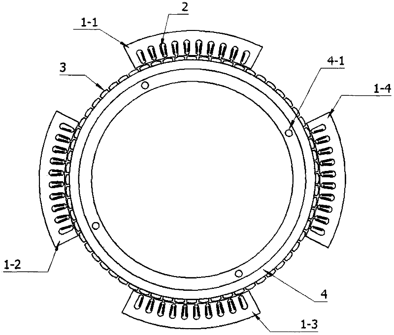
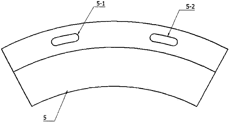
[0030] Such as figure 1 and figure 2 As shown, the motor of the present invention is mainly composed of four stator blocks 1-1, 1-2, 1-3, 1-4, a coil winding 2, a permanent magnet 3, a back iron 4, and a stator shell 5. The four stator blocks have exactly the same structural form, and are composed of iron cores, ie, arc-shaped silicon steel sheets 1-1, 1-2, 1-3, 1-4, coil windings 2 and a stator shell 5 . refer to image 3 and Figure 6 As shown, a coil is wound on the iron core, and the iron core and the coil are fixed together in the stator shell 5 by epoxy casting; the rotor is composed of a permanent magnet 3 and a back iron 4, the permanent magnet 3 is attached to the outer surface of the back iron 4, and the rotor The minimum air gap with the stator is 1.2mm, and the effective thickness of the whole device is 50mm;

[0031] Such as figure 1As shown, the outer radius of the rotor is 198.8mm, the inner radius is 178mm, and the back iron 4 is made of No. 45 steel wit...


PUM

PropertyMeasurementUnit
radiusaaaaaaaaaa
radiusaaaaaaaaaa
thicknessaaaaaaaaaa

Abstract

The invention relates to a multi-stator arc motor for photoelectric tracking equipment. The multi-stator arc motor is an alternating current permanent magnetic synchronous arc linear motor comprising arc silicon steel sheets, coil windings, permanent magnets, back iron and stator shells. Four stator structures are in the same form and comprise the arc silicon steel sheets, the windings and the stator shells. Rotors comprise the permanent magnets and the back iron, and the 64 permanent magnets (32 pairs) are stuck to the external surface of the back iron. The minimum air gap between each rotorand each stator is 1.2mm, and the effective thickness of the complete device is 50mm. The complete motor adopts a fractional slot structural design, and the shape of the permanent magnets, the lengthof each stator and the shape of a slot are optimally designed by finite elements, thereby greatly reducing the torque fluctuation caused by end effect and slot effect; each stator has 11 poles and 10slots; and the windings are wound in an AaaAAaBbbBBbCccCCc mode to ensure that the space phase difference of a three-phase winding is 120 degrees. The four stators are installed in a staggered arrangement mode and can well reduce the torque fluctuation and radial attraction.

Description

technical field [0001] The invention belongs to the field of motor design and relates to a multi-stator arc motor used for photoelectric tracking equipment. Background technique [0002] The transmission methods used by traditional photoelectric tracking equipment mainly include: worm gear transmission, gear transmission, friction transmission and torque motor coaxial installation transmission. These traditional transmission methods have played a pivotal role in the development of photoelectric tracking equipment, but there are still many shortcomings in these transmission methods, especially when developing a new generation of large-scale photoelectric tracking equipment with the continuous advancement of science and technology. These transmission modes are no longer competent. When the worm gear transmission mode is used, the size of the turbine is difficult to make large, and the accuracy of the large size turbine is difficult to be guaranteed. For large-scale photoelect...

Claims


Application Information

Patent Timeline
Patent Type & Authority Patents(China)
IPC IPC(8): H02K21/00H02K21/02H02K1/27H02K1/17H02K1/16H02K3/04
Inventor 常九健马文礼黄金龙
Owner INST OF OPTICS & ELECTRONICS - CHINESE ACAD OF SCI
Learn More