
Method for optimally designing machine tool body structure

An optimized design and bed technology, applied in calculation, special data processing applications, instruments, etc., can solve the problems of increasing the labor intensity of analysts, complex bed models, and time-consuming problems, so as to achieve the best optimization effect and relieve manpower , time-saving effect

Active Publication Date: 2011-05-18
XI AN JIAOTONG UNIV +1
View PDF3 Cites 79 Cited by
  • Summary
  • Abstract
  • Description
  • Claims
  • Application Information

AI Technical Summary

Problems solved by technology

Due to the complexity of the bed model, it is difficult to establish its parametric model with finite element software such as Ansys. Therefore, most engineers and technicians use the "optimized design method", that is, to continuously modify its structural dimensions in 3D software such as Pro / e, and then import The calculation is carried out in the finite element software, the process is repeated continuously, and the optimal solution is finally obtained. The optimization process cannot be called the optimal design, and it consumes a lot of time and increases the labor intensity of the analyst. The optimal solution is not absolute best value

Method used


Image

  • Method for optimally designing machine tool body structure
  • Method for optimally designing machine tool body structure
  • Method for optimally designing machine tool body structure

Examples


Embodiment Construction

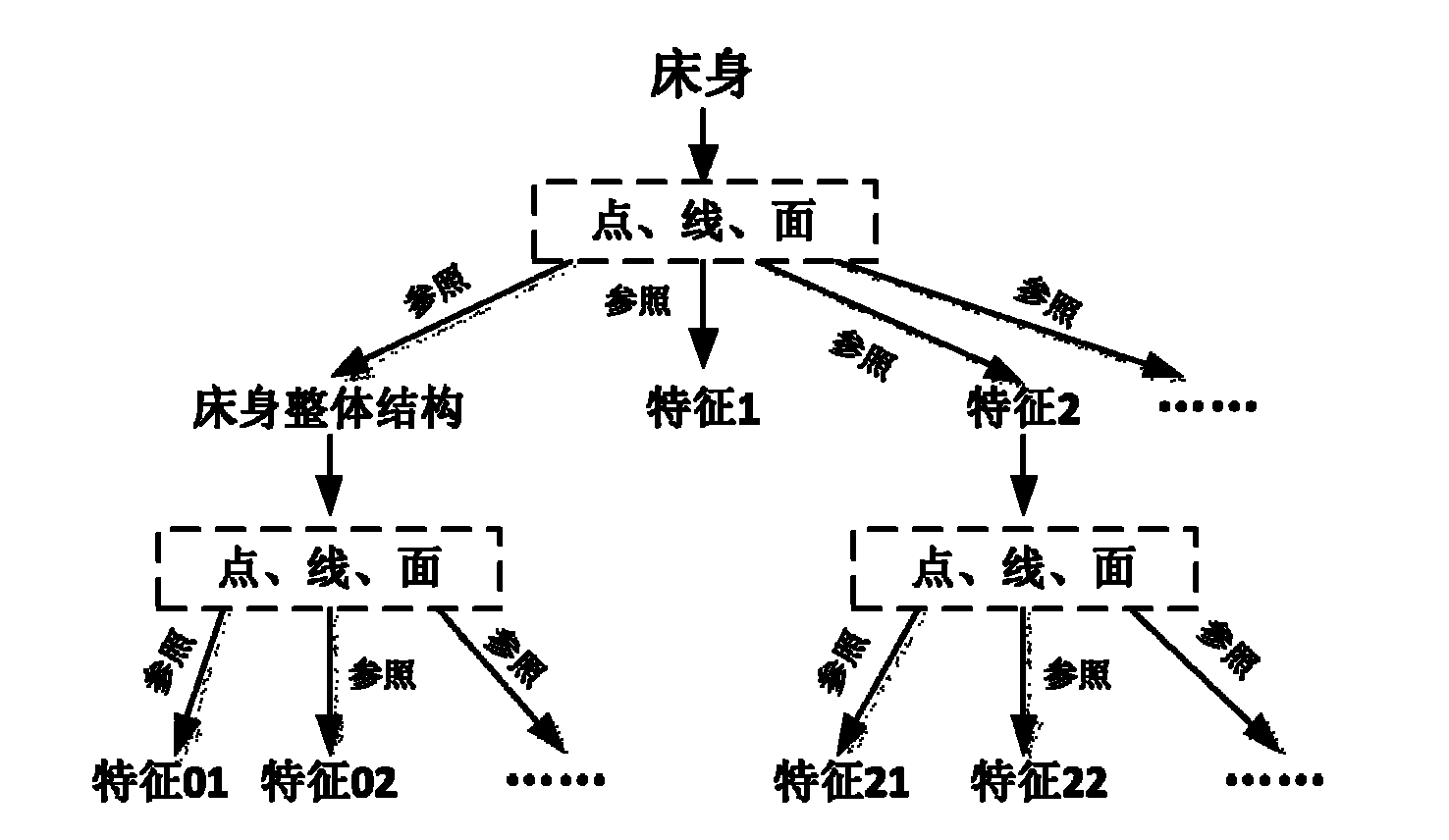
[0055] figure 1 Refer to the spectral diagram for the parametric modeling features. When establishing the overall structure of the bed, the overall size datum of the bed is used as a reference. Feature 1 and feature 2 are attached to the overall size of the bed. The model establishment also selects the overall size datum of the bed. as the benchmark; feature 01 and feature 02 are attached to the overall structure, and some feature surfaces of the overall structure of the bed are selected as the reference for model establishment; feature 21 and feature 22 are attached to feature 2, and some feature surfaces of feature 2 are selected as the reference for model establishment .

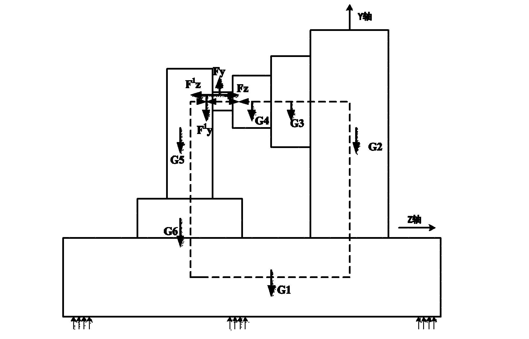
[0056] figure 2 To determine the process for the bed load boundary conditions, first determine the load source of the machine tool under working conditions, such as cutting force, gravity, friction force, clamping force, inertial force, external excitation force and thermal stress, etc., and then constr...


PUM


Abstract

The invention discloses a method for optimally designing a machine tool body structure, which comprises the following steps of: carrying out multiobjective optimization on wall thickness of a machine tool body and physical dimension of a rib plate; and carrying out comprehensive optimization analysis on the structure of the machine tool body, wherein the step of carrying out the multiobjective optimization on the wall thickness of the machine tool body and the physical dimension of the rib plate comprises the procedures of: establishing a machine tool body parameterized model; determining a boundary condition; determining a design variable, a restrict condition and a target function, establishing an optimization design model; and correcting the wall thickness of the machine tool body and the dimension of the rib plate; and the step of carrying out the comprehensive optimization analysis on the structure of the machine tool body comprises the procedures of: establishing a geometrical model of the machine tool body; determining a boundary condition; determining a topological optimization target, establishing a topological optimization model; and correcting the structure of the machine tool body. According to the invention, the traditional optimization design method of the machine tool body is changed, movable and static rigidity characteristics are improved, and the manufacture cost is lowered. The invention can be widely applied to the optimization designs of various machine tool support member structures.

Description

technical field [0001] The invention relates to a method for optimizing the structure of a machine tool support, in particular to a method for optimizing the structure of a bed. Background technique [0002] The bed is the main support of the machine tool, which supports the weight of the workpiece and the machine tool, and has become a key technology for machine tool manufacturers. However, most enterprises still follow the old path of empirical design and imitation. The design of the bed blindly pursues its high dynamic and static stiffness, but ignores the problem of manufacturing cost. For example, the weight of the TH series milling and boring machine bed accounts for more than 30% of the total weight of the machine tool. . Therefore, in order to reduce materials and reduce costs on the basis of ensuring the bearing capacity of the bed, it is necessary for the support to have a higher stiffness per unit weight, which affects the rationality of the distribution of the s...

Claims


Application Information

Patent Timeline
IPC IPC(8): G06F17/50
Inventor 王崴洪军李宝童朱林波杜飞
Owner XI AN JIAOTONG UNIV
Learn More