
Heat supplying system capable of directly recovering sewage flash steam residual heat by utilizing absorption heat pump set

An absorption heat pump and flash steam technology, which is applied in the field of recovery of sewage flash steam waste heat heating system, can solve the problems affecting the temperature rise and temperature loss of hot water for heating, achieve economic and social benefits of emission reduction, and improve temperature, reducing system investment and the effect of pump power consumption

Inactive Publication Date: 2011-05-18
SHUANGLIANG ECO ENERGY SYST CO LTD
View PDF5 Cites 3 Cited by
  • Summary
  • Abstract
  • Description
  • Claims
  • Application Information

AI Technical Summary

Problems solved by technology

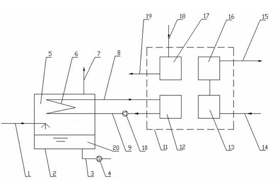
However, this method requires the installation of facilities such as heat exchange tube bundles, water inlet chambers, water outlet chambers, and hot water circulation pumps to recover the condensation heat of sewage flash evaporation. This part of the device requires initial investment and power consumption of water pumps, because it is an indirect extraction The waste heat of flash evaporation of sewage, the heat exchange of flash steam and hot water will cause a certain temperature loss, which affects the temperature rise of hot water for heating and other unfavorable factors

Method used


Image

  • Heat supplying system capable of directly recovering sewage flash steam residual heat by utilizing absorption heat pump set
  • Heat supplying system capable of directly recovering sewage flash steam residual heat by utilizing absorption heat pump set
  • Heat supplying system capable of directly recovering sewage flash steam residual heat by utilizing absorption heat pump set

Examples


Embodiment Construction

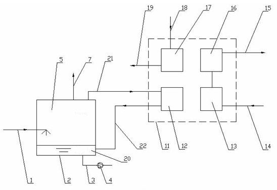
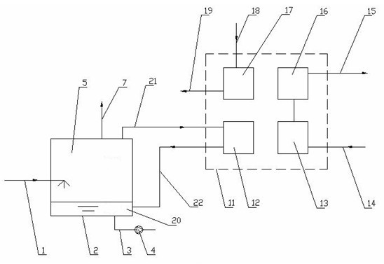
[0011] Such as figure 2 Shown is a schematic diagram of a heat supply system using absorption heat pump units to directly recover waste heat from sewage flash steam in the sewage flash evaporation system. Consists of sewage inlet pipe 1, closed cavity 2, sewage outlet pipe 3, sewage pump 4, gas phase area 5, non-condensable gas discharge pipe 7, absorption heat pump unit 11, heat medium water return pipe 14, heat medium water outlet pipe 15. Drive steam pipe 18, steam condensate discharge pipe 19, liquid phase area 20, flash steam inlet pipe 21, flash steam condensate outlet pipe 22 and control system (not shown in the figure), etc. The absorption heat pump unit directly recovers the waste heat system of sewage flash steam. The absorption heat pump unit 11 is composed of a generator 17 , a condenser 16 , an absorber 13 and an evaporator 12 . Its characteristic is that the low-pressure steam flashed by the sewage in the low-pressure closed cavity 2 is directly connected to t...


PUM


Abstract

The invention relates to a heat supplying system capable of directly recovering sewage flash steam residual heat by utilizing an absorption heat pump set, and the system provided by the invention is used for reclaiming sewage flash steam residual heat. The system provided by the invention comprises an enclosed cavity body (2) and an absorption heat pump set (11), wherein the absorption heat pump set (11) comprises a generator (17), a condenser (16), an absorber (13) and a vaporizer (12), the lower part of the enclosed cavity body (2) is a liquid region (20), and the upper part of the enclosed cavity body (2) is a gas region (5). The system provided by the invention is characterized in that low-pressure water vapor obtained by the sewage subjected to flash steam at the low-pressure enclosed cavity body (2) is directly connected with the vaporizer (12) of the absorption heat pump set (11) through a flash steam inlet vaporizer tube (21), and flash steam condensate water after heat release in the vaporizer (12) refluxes to the liquid region (20) of the enclosed cavity body (2) through a flash steam condensate water outlet vaporizer tube (22). The system provided by the invention has the advantages that the sewage flash steam heat of condensation can be recycled more efficiently, the temperature loss can be reduced, the hot water supply temperature can be improved, and the system investment and the operating cost can be reduced.

Description

technical field [0001] The invention relates to a waste heat heating system for recovering sewage flash steam. It is used to recover the waste heat of sewage flash steam. Background technique [0002] People need a lot of hot water for heating in the production process and life, and generally need to consume primary energy to produce it. At the same time, there is a large amount of hot water waste heat in the production process, but some hot water has water quality problems, and the water contains solid particles. (Such as steel slag flushing water, etc.), corrosive components, etc., it is called sewage. Due to the problems of corrosion, fouling, wear and other problems in sewage, ordinary heat exchangers cannot realize the heat extraction process. In order to recycle the waste heat of this part of sewage without wasting it in vain, there is currently a sewage flash heat extraction heat exchange system. in a way such as figure 1 The waste heat of sewage is extracted as sh...

Claims


Application Information

Patent Timeline
IPC IPC(8): F24H4/02F24D17/02
CPCY02B30/18
Inventor 江荣方王炎丽
Owner SHUANGLIANG ECO ENERGY SYST CO LTD
Learn More