
Scroll compressor

A scroll compressor and compression mechanism technology, applied in the field of scroll compressors, can solve problems such as spindle sintering and poor lubrication, and achieve the effect of improving quality and reliability

Inactive Publication Date: 2011-05-18
MITSUBISHI ELECTRIC CORP
View PDF7 Cites 7 Cited by
  • Summary
  • Abstract
  • Description
  • Claims
  • Application Information

AI Technical Summary

Problems solved by technology

Therefore, there is a problem that the main shaft is sintered due to poor lubrication of the bearings of the compression mechanism.

Method used


Image

  • Scroll compressor
  • Scroll compressor
  • Scroll compressor

Examples


Embodiment approach 1

[0063] First, the present embodiment is characterized in the following points.

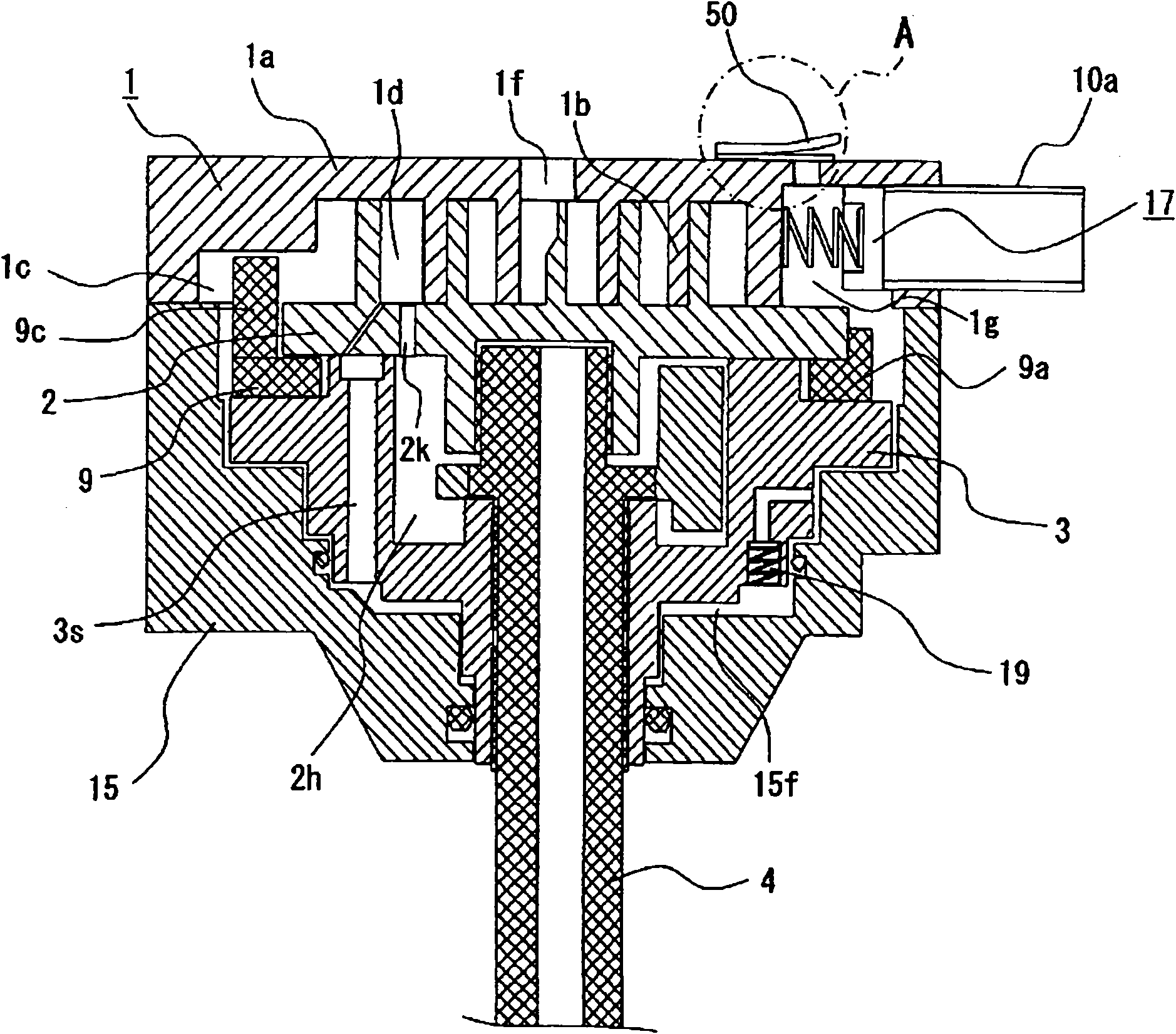
[0064] (1) Since the discharge space pressure Pd is not greater than the suction space pressure Ps during the reverse rotation of a general scroll compressor, there is no differential pressure between the upper end surface and the lower end surface of the main shaft. Differential pressure oil supply, spindle sintering. However, in the scroll compressor of the present embodiment, since the orbiting scroll is provided with a first communication hole communicating from the compression chamber to the flange portion space in order to reduce the pressure in the flange portion space of the orbiting scroll during counter-rotating operation, In addition, in order to float the flexible frame during reverse operation, a communication hole is provided on the flexible frame to introduce high pressure from the high-pressure suction pressure space to the frame back pressure space, and a check valve is provided o...

Embodiment approach 2

[0264] In general scroll compressors, since the discharge space pressure Pd is not greater than the suction space pressure Ps during reverse rotation, there is no differential pressure between the upper end surface and the lower end surface of the main shaft 4, and therefore, no differential pressure can be applied to the bearing. Oil supply, main shaft 4 sintering.

[0265] The scroll compressor 400 of Embodiment 2 introduces the pressure Pm' (the pressure in the screw in the expansion stroke) lower than the discharge space pressure Pd in ​​the screw into the upper end space of the main shaft 4 so that it can pass through the discharge difference during reverse rotation. The pressure oil supply method supplies oil to each bearing part, and the communication hole 2n to the flange part space 2h is provided on the swing scroll 2, in order to prevent the refrigerant from flowing into the spiral from the communication hole 2n during forward rotation. And a communication check valv...


PUM


Abstract

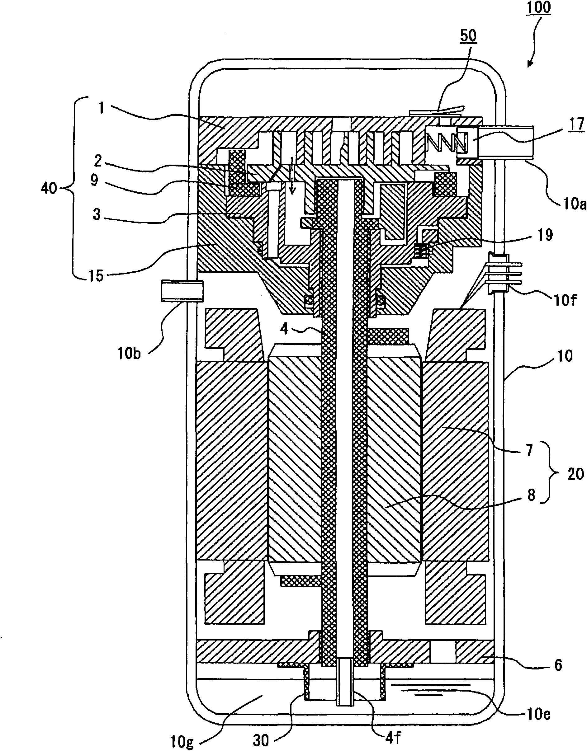
The invention provides a scroll compressor, which enables to avoid shaft sintering caused by poor lubrication of the bearing portion in the reverse operation and aims to achieve reliability enhancement and quality improvement. With respect to the scroll compressor (100) of the invention, a compression mechanism portion (40) comprises a fixed scroll pan (1), a swing scroll pan (2), a cross slip ring (9), a main shaft (4), a guiding frame (15), a soft frame (3), an suction check valve combination (17), a safety valve combination (50) arranged on the fixed scroll pan (1), and a check valve (19) which is disposed on the soft frame (3) and allows the communication between the suction pressure space and the frame space. A platen portion of the swing scroll pan (2) is provided with a through hole which enables the communication between the flange portion space (2h) and the compression chamber of the expansion stroke, in order that during the reverse operation of a motor (20), the pressure of the backpressure space of the swing scroll pan (2) is lower than that of a sealed container (10), and refrigerant oil (10e) is supplied to the compression mechanism portion (40) by the differential pressure.

Description

technical field [0001] The present invention relates to scroll compressors. Background technique [0002] Conventionally, for the purpose of improving instability such that the flexible frame and the oscillating scroll are easily released due to the vibration of the oscillating scroll caused by minute disturbances, the following scroll compressors have been proposed. In the airtight container, various plate-shaped helical teeth are engaged with each other to form compression chambers. The fixed scroll and the swing scroll support the swing scroll in the axial direction and support the swing scroll in the axial direction. The flexible frame of the driven main shaft and the guide frame that supports the flexible frame in the radial direction and is fixed on the sealed container can move the oscillating scroll in the axial direction through the axial movement of the flexible frame relative to the guide frame. That is, a frame space is formed between the flexible frame and the ...

Claims


Application Information

Patent Timeline
IPC IPC(8): F04C18/02
Inventor 高桥广康西木照彦茗原将史
Owner MITSUBISHI ELECTRIC CORP
Learn More