
Liquid chromatography high-pressure parallel cam pump

A technology of liquid chromatography and cam pump, which is applied in the direction of pumps, pump devices, pump components, etc., can solve the problems of large pressure fluctuations, reduce the normal service life of sealing rings, and the detection system brings stable flow and high detection accuracy, etc., to achieve Effect of reducing pressure pulsation and protecting service life

Active Publication Date: 2013-02-27
JIANGSU TONGJI ANALYTICAL INSTR CO LTD
View PDF2 Cites 1 Cited by
  • Summary
  • Abstract
  • Description
  • Claims
  • Application Information

AI Technical Summary

Problems solved by technology

Regardless of whether the plunger deviates from the origin or returns to the origin, the whereabouts and source of the radial force are the sealing ring, and the sealing ring is bearing the extra radial force brought by the plunger, which is reducing the normal force of the sealing ring. service life
[0005] Obviously, a pump with large pressure fluctuations and poorly controlled plunger movement trajectory cannot bring stable flow and high detection accuracy to the detection system.

Method used


Image

  • Liquid chromatography high-pressure parallel cam pump
  • Liquid chromatography high-pressure parallel cam pump
  • Liquid chromatography high-pressure parallel cam pump

Examples


Embodiment Construction

[0030] In order to make the object, technical solution and advantages of the present invention clearer, the implementation manner of the present invention will be further described in detail below in conjunction with the accompanying drawings.

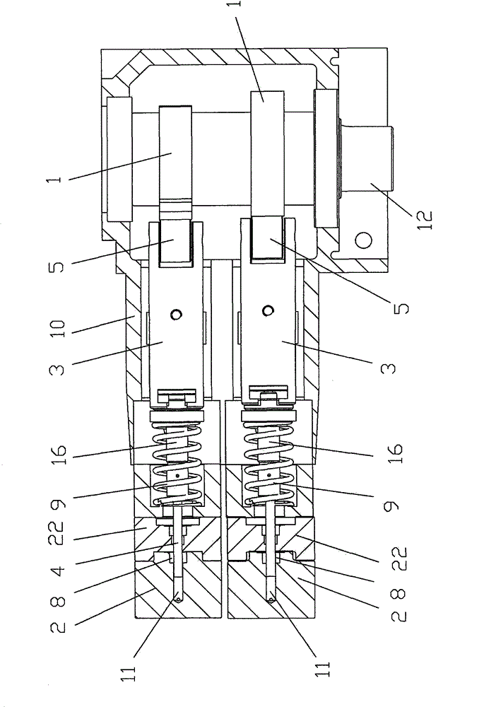
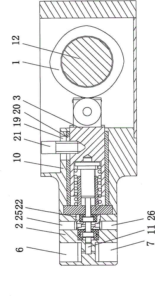
[0031] Such as figure 2 , image 3 , Figure 4 As shown, the liquid chromatography high-pressure parallel cam pump of the present invention includes: a motor, a pump main body 10, two cleaning blocks 22 with a liquid inlet and a liquid outlet, a camshaft 9 connected to the motor, and a camshaft 9 fixedly connected to the camshaft 9 Two cylindrical cams 1 with the same shape, two pump heads 2 fixedly connected with the pump main body 10, the camshaft 9 is connected with the pump main body 10 through a bearing 30, and each cylindrical cam 1 is connected to the pump body through a set of reciprocating liquid delivery mechanism. A pump head 2 is connected; each set of reciprocating liquid delivery mechanism includes a roller 5, a plunge...


PUM


Abstract

The invention discloses a liquid chromatography high-pressure parallel cam pump, which comprises a motor, a pump main body, a cleaning block, a cam shaft, two cylindrical cams, two pump heads and two sets of reciprocating liquid delivering mechanisms, wherein each set of the reciprocating liquid delivering mechanisms comprises a plunger push rod, a plunger backseat, a plunger and a roller wheel; the pump heads are provided with pump chambers, liquid inlet holes and drain holes; one end of the plunger extends into the pump chambers of the pump heads; a sealing ring is arranged between the pump heads and the plunger; a compression spring is sleeved outside the plunger; the back end of the compression spring presses against a shaft shoulder of the plunger backseat; N groups of cam curves are uniformly formed on the outer circumference of the cylindrical cams, N is an integer more than or equal to 2, and each group of the cam curves comprises ascending curves and descending curves; and the degree of the phase difference of the two cylindrical cams is 180 / N. Compared with the prior art, for the liquid chromatography high-pressure parallel cam pump, under the condition that the motor rotating speed, the delivery capacity per revolution of the pump and the diameter of the plunger are the same, the to-and-fro movement frequency of the plunger is improved by N times, and the pressure fluctuation of the liquid chromatography high-pressure parallel cam pump in work is reduced.

Description

technical field [0001] The invention relates to a liquid chromatography high-pressure parallel cam pump for a liquid chromatography instrument. Background technique [0002] Existing high-pressure parallel cam pumps for liquid chromatography, such as figure 1 As shown, it includes: a motor, a pump main body 10, two cleaning blocks 22 with a liquid inlet and a liquid outlet, a camshaft 9 connected to the motor, two identically shaped and positioned 180° fixedly connected to the camshaft Cylindrical cam 1, two pump heads 2 fixedly connected with pump main body 10, each cylindrical cam is connected with a pump head 2 through a set of reciprocating liquid delivery mechanism; each set of reciprocating liquid delivery mechanism includes plunger push rod 3, column Plug back seat 16 and plunger 4 connected to one end of plunger push rod, one end of plunger push rod 3 is provided with roller 5; pump head 2 has pump chamber 11 and inlet hole 6 and discharge liquid connected with pump...

Claims


Application Information

Patent Timeline
Patent Type & Authority Patents(China)
IPC IPC(8): F04B23/06F04B53/00
Inventor 汪仁路
Owner JIANGSU TONGJI ANALYTICAL INSTR CO LTD
Learn More