High-strength concrete facade cross node constrained by steel mould containing steel reinforcement framework

A high-strength concrete and steel skeleton technology, applied in the direction of building reinforcements, structural elements, columns, etc., can solve the problems of low bearing capacity of cross joints, difficulty in meeting the requirements of strong joints, and difficulty in ensuring construction quality, so as to facilitate construction and ensure Ductility of joints, effect of reducing project cost

Inactive Publication Date: 2011-05-18
HARBIN INST OF TECH
View PDF10 Cites 2 Cited by
  • Summary
  • Abstract
  • Description
  • Claims
  • Application Information

AI Technical Summary

Problems solved by technology

[0003] The purpose of the present invention is to provide a high-strength concrete facade with steel skeleton and steel mold restraint to solve the problems that the bearing capacity of the intersection joints of the existing reinforced concrete facade is not high, it is difficult to meet the requirements of strong joints, it is difficult to ensure the construction quality, and the cost is too high. face intersection node

Method used


Image

  • High-strength concrete facade cross node constrained by steel mould containing steel reinforcement framework
  • High-strength concrete facade cross node constrained by steel mould containing steel reinforcement framework
  • High-strength concrete facade cross node constrained by steel mould containing steel reinforcement framework

Examples


specific Embodiment approach 1

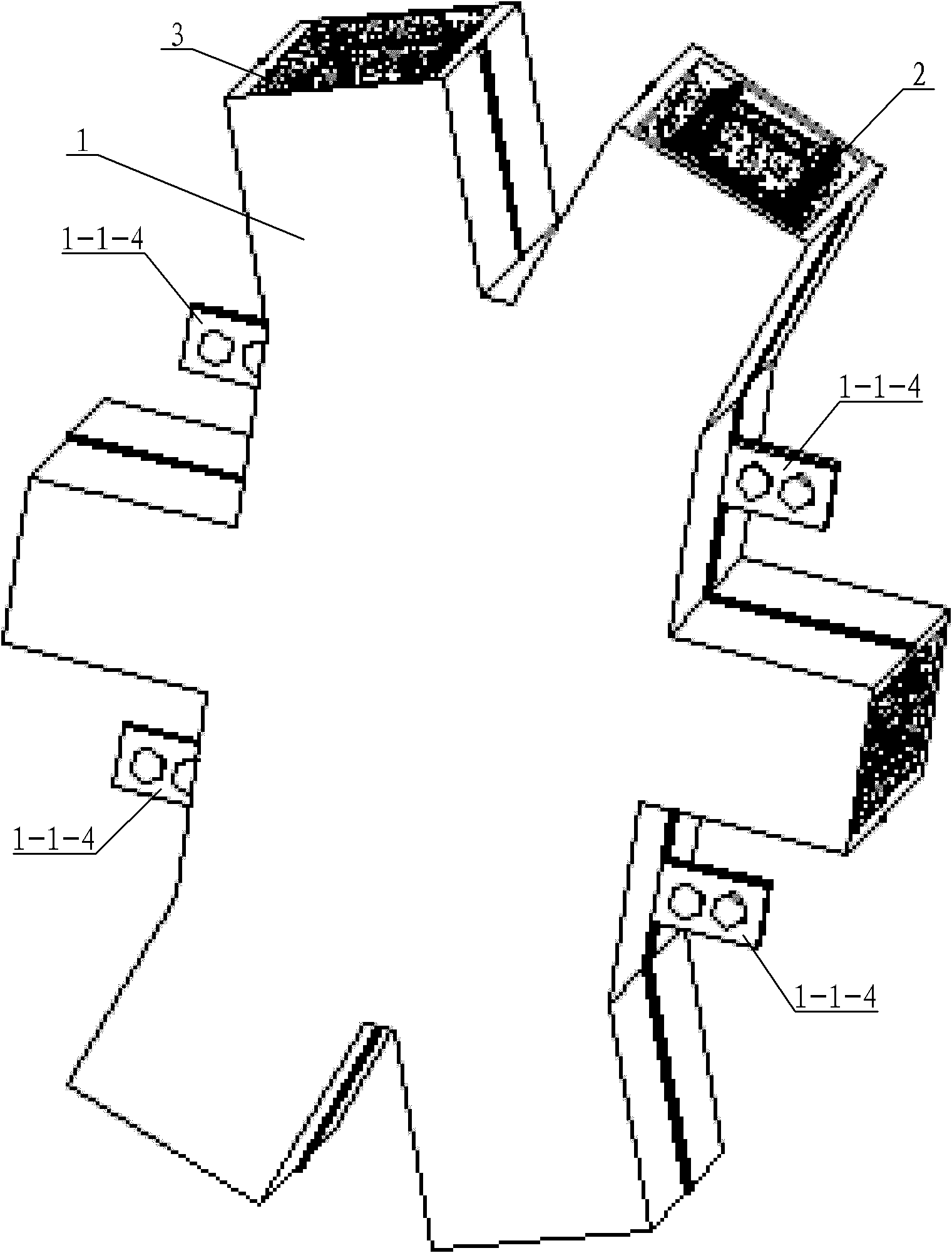
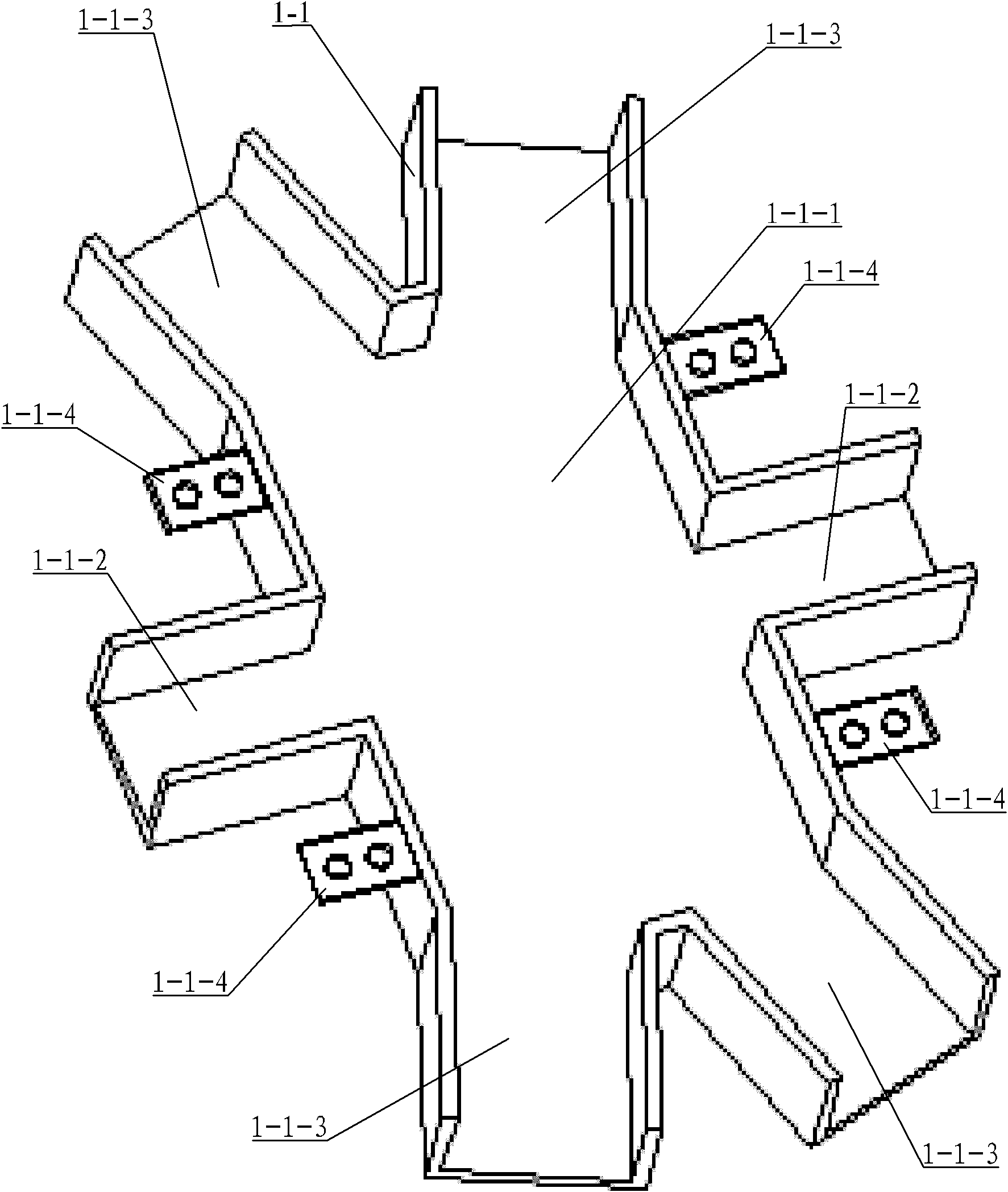
[0007] Specific implementation mode one: combine Figure 1 to Figure 4 Describe this embodiment, this embodiment comprises steel plate formwork 1, steel bar skeleton 2 and high-strength concrete 3, described steel plate formwork 1 is made up of two pieces of channel-shaped steel plates 1-1 buckled together, and each piece of channel-shaped steel plate 1-1 is made of An integrated groove-type vertical die 1-1-1, two groove-type horizontal dies 1-1-2 and four groove-type oblique dies 1-1-3, two groove-type horizontal dies 1-1 -2 are arranged symmetrically on the vertical sides of the groove-type vertical die 1-1-1, and two groove-type horizontal dies 1-1-2 are arranged along the horizontal centerline of the groove-type vertical die 1-1-1, The grooves on the two grooved horizontal mold sheets 1-1-2 communicate with the grooves on the grooved vertical mold sheets 1-1-1, and the two grooved oblique mold sheets 1-1-3 in the four grooved oblique mold sheets The mold piece 1-1-3 is l...

specific Embodiment approach 2

[0008] Specific implementation mode two: combination Figure 1 ~ Figure 3 To illustrate this embodiment, each channel-shaped steel plate 1-1 of this embodiment also includes four bolt lugs 1-1-4, and two bolt lugs are arranged above the two groove-shaped horizontal mold pieces 1-1-2 plate 1-1-4, two bolt lugs 1-1-4 are arranged below the two grooved horizontal mold pieces 1-1-2, and the upper two bolt lugs 1-1-4 are arranged symmetrically on On both sides of the groove-shaped vertical mold sheet 1-1-1, the two lower bolt lugs 1-1-4 are symmetrically arranged on both sides of the groove-shaped vertical mold sheet 1-1-1. Other components and connections are the same as those in the first embodiment.

[0009] During the use of the present invention, one, earlier the horizontal steel bar frame 2-1 and two oblique steel bar frames 2-2 are bound and formed respectively, utilize vertical bar 2-3 and stirrup bar 2-4 to horizontal steel bar frame 2-1 and two The inclined steel frame ...


PUM


Abstract

The invention discloses a high-strength concrete facade cross node constrained by a steel mould containing a steel reinforcement framework, relating to a reinforced concrete facade cross node, and solving the problems that the traditional reinforced concrete facade cross node has low bearing force, can not satisfy the requirements of a strong node, can not guarantee construction quality, and has high construction price. A horizontal steel reinforcement rack and two inclined steel reinforcement racks are respectively bound and shaped; four vertical steel reinforcements and a plurality of stirrups bind the horizontal steel reinforcement rack and the two inclined steel reinforcement racks into the steel reinforcement framework; the steel reinforcement framework is arranged in the internal hollow cavity of each steel plate mould; a butt joint along two single-piece steel plate moulds is in full weld; high-strength concrete is poured in the internal hollow cavity of the steel plate mould; and after conserved, the steel plate moulds, the steel reinforcement framework and the high-strength concrete form a whole to form the high-strength concrete facade cross node constrained by the steel mould containing the steel reinforcement framework. The high-strength concrete facade cross node is used for a batter post cross node with a high-rise tube in a tube structure of reinforced concrete.

Description

technical field [0001] The invention relates to a reinforced concrete facade intersection joint in the field of civil engineering. Background technique [0002] The reinforced concrete façade intersection joint formed by the intersection of oblique cross columns is a plane force unit. The oblique compression and lateral expansion deformation of this type of joint due to external loads are mainly borne by the core concrete in the joint area and its surrounding stirrups. , resulting in greater brittleness of the joints, low bearing capacity, and difficulty in meeting the requirements of strong joints; at the same time, during the construction of such joints, the joints are shaped according to the construction method of binding the steel skeleton, supporting the formwork, pouring concrete, and removing the formwork after curing. The reinforced concrete façade intersection joint obtained by the existing construction method is cumbersome in the construction process, it is difficu...

Claims


Application Information

Patent Timeline
Patent Type & Authority Applications(China)
IPC IPC(8): E04B1/58E04C3/34E04C5/06
Inventor 周威张建新郑文忠曹正罡侯晓萌胡海波
Owner HARBIN INST OF TECH
Why Eureka
Try Eureka