
Smart charger

A technology of smart chargers and relays, applied in electrical components, circuit devices, emergency protection circuit devices, etc., can solve problems such as long charging time, inconvenience for car owners, and excessive running, so as to improve utilization rate, save energy, and reduce carbon emissions Effect

Inactive Publication Date: 2011-05-11
SUZHOU CHIEN SHIUNG INST OF TECH
View PDF5 Cites 8 Cited by
  • Summary
  • Abstract
  • Description
  • Claims
  • Application Information

AI Technical Summary

Problems solved by technology

After get off work, the user stores the battery car in the garage. For ordinary chargers, the user generally has two methods: one is to plug the charger and battery into the power supply immediately, start charging, and then wait until the next morning before going to work (7 The second method is to wait until after 9 o’clock in the evening, then go to the garage to plug the charger and battery into the power supply, start charging, and then unplug the battery before going to work the next morning (around 7 o’clock) Remove the charger; for the first method, the charging is mainly carried out before 9:00 pm (about 90% of the charging capacity has been completed), and the electricity bill is mainly settled according to the peak-hour electricity price (0.55 yuan / kWh), and the charging time is too long ( Mainly in floating state), up to about 14 hours
The second method can obviously save up to 40% of the electricity bill. The electricity price in off-peak hours (0.35 yuan / kWh) and the charging time is about 10 hours, but the user needs to go to the garage one more time, which brings inconvenience to the car owner, especially in bad weather.

Method used


Image

  • Smart charger
  • Smart charger

Examples


Embodiment

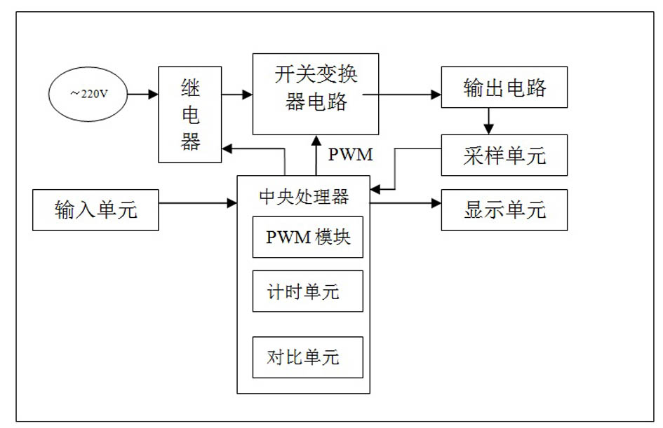
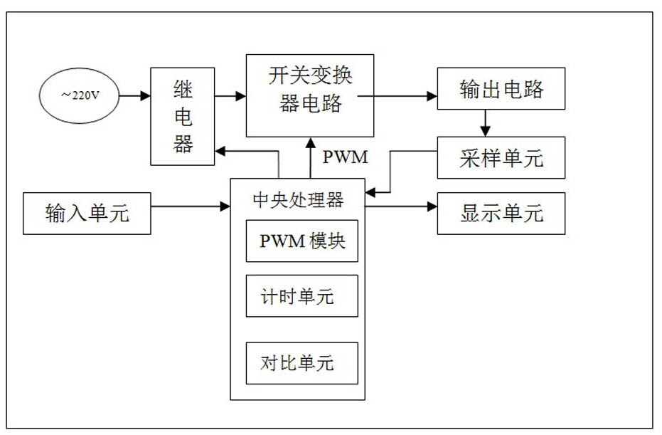
[0024] An intelligent charger includes: an input unit, a display unit, a relay, a switching converter circuit, a sampling unit and a central processing unit.

[0025] The central processing unit is provided with a timing unit, a comparison unit, and a PWM control module; the comparison unit is set with a current critical value, a floating current value and a voltage critical value (the critical value of the current refers to the upper limit of the charging current, and the floating current refers to the upper limit of the charging current. The current value when the battery is basically fully charged, and the critical value of the voltage refers to the upper limit of the charging voltage).

[0026] The central processing unit sends out a PWM signal to control the operation of the switching converter circuit; the input unit inputs the charging delay time to the central processing unit; the central processing unit sets the relay according to the input charging delay time; the dis...


PUM


Abstract

The invention discloses a smart charger. The smart charger comprises an input unit, a display unit, a relay, a switch converter circuit, a sampling unit and a central processing unit, wherein the central processing unit sends a PWM (Pulse Width Modulation) signal to control the state of the switch converter circuit; the input unit inputs charging delay time to the central processing unit; the central processing unit controls the on-off state of the relay according to the input or the default charging delay time; the display unit reads the delay time and the charging state of the central processing unit, and displays the data; and the sampling unit collects the current and voltage data of the output circuit, and transmits the data to the central processing unit. The smart charger can set the charging start time according to the requirement of a user to ensure the charging process in a reasonable period, and can automatically cut off power of the charger when the battery is fully charged, thereby effectively prolonging the service life of battery, lowering the electric expenses and saving energy.

Description

technical field [0001] The invention relates to a charger, in particular to an intelligent charger which can set the starting time and automatically shut down after being fully charged. Background technique [0002] The electric vehicle charger is characterized by intelligent control of the charging process, and is a typical low-carbon product. After work, the user stores the battery car in the garage. For ordinary chargers, the user generally has two methods: one is to plug the charger and battery into the power supply immediately, start charging, and then wait until the next morning before going to work (7 The second method is to wait until after 9 o’clock in the evening, then go to the garage to plug the charger and battery into the power supply, start charging, and then unplug the battery before going to work the next morning (around 7 o’clock) Remove the charger; for the first method, the charging is mainly carried out before 9:00 pm (about 90% of the charging capacity...

Claims


Application Information

Patent Timeline
Patent Type & Authority Applications(China)
IPC IPC(8): H02J13/00H02J3/18H02H7/04
CPCY02E40/30Y02E60/00Y04S10/20
Inventor 陈邦琼刘红月浦灵敏
Owner SUZHOU CHIEN SHIUNG INST OF TECH
Learn More