
Ka frequency range high-power waveguide rotary joint

A rotary joint, high-power technology, applied in waveguide-type devices, electrical components, circuits, etc., can solve the problems of increased frequency dependence, unfavorable use of high-power, and narrowing of the suppression bandwidth, reducing insertion loss, beneficial to High power use, the effect of achieving smoothness

Inactive Publication Date: 2011-05-11
XIAN INSTITUE OF SPACE RADIO TECH
View PDF3 Cites 6 Cited by
  • Summary
  • Abstract
  • Description
  • Claims
  • Application Information

AI Technical Summary

Problems solved by technology

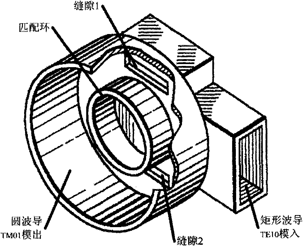
However, the TM01-mode converter adopts double-slit symmetrical excitation. Since the double-slit is narrow, the micro-discharge margin is small, which is not conducive to high-power use, and due to the influence of the short-circuit surface during double-slit excitation, the electric field near the double-slit appears localized. Inhomogeneity, resulting in its suppression of the TE11 mode increases in the Y direction and frequency correlation, narrowing the suppression bandwidth

Method used


Image

  • Ka frequency range high-power waveguide rotary joint
  • Ka frequency range high-power waveguide rotary joint
  • Ka frequency range high-power waveguide rotary joint

Examples


Embodiment Construction

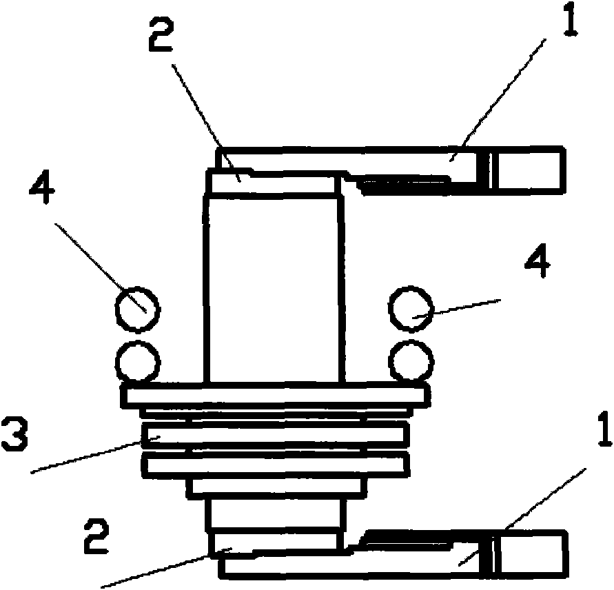
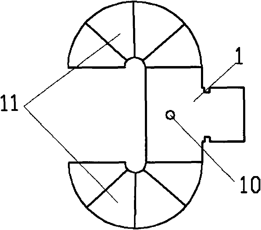
[0029] As attached figure 2 As shown, the rotary joint of the present invention is divided into an upper half and a lower half that are connected to each other. The upper and lower half are respectively formed by connecting an H-face T-shaped branch 1 and a TM01 mode conversion part 2; TM01 mode The conversion part 2 includes a rectangular straight waveguide 20 and a circular waveguide 21, such as Figure 4 As shown, the circular waveguide 21 is butted with the broad side of the rectangular straight waveguide 20; Figure 7 As shown, in the top view of the TM01 mode conversion part 2, the rectangular straight waveguide 20 is symmetrical with respect to the circular waveguide 21, and the two branch ports of the H-plane T-shaped branch 1 are respectively connected to the two ports of the rectangular straight waveguide 20.

[0030] The upper and lower parts of the rotary joint are connected with the bearing 4 through the choke groove 3.

[0031] Such as image 3 As shown, the H-face T-...


PUM


Abstract

The invention discloses a Ka frequency range high-power waveguide rotary joint consisting of an upper half and a lower half which are mutually connected and respectively connected by a T-shaped branch with an H surface and a TM01 mode conversion part; the TM01 mode conversion part comprises a rectangular straight waveguide and a round waveguide; the round waveguide is arranged at the center of the rectangular straight waveguide and is butted with the wide side of the rectangular straight waveguide which is in a symmetric form relative to the centre of the circle of the round waveguide; and two branches of the T-shaped branch with an H surface are connected with two ports of the rectangular straight waveguide. With a bilateral symmetric exciting TM01 mode method, a path of signals is decomposed into two paths of signals with equal width and same phase by the T-shaped branch with an H surface so that the correlation to a frequency is greatly lowered when a TE11 mode is inhibited, the high inhibition on the TE11 mode is realized within larger bandwidth, and the stability of the electrical property of the rotary joint in rotating is realized.

Description

Technical field [0001] The invention belongs to the field of microwave communication, and relates to a high-power rotary joint, in particular to a Ka-band high-power waveguide rotary joint with bilateral symmetric excitation. Background technique [0002] In microwave communication, the rotary joint is used to realize the transmission of microwave signals between the dynamic antenna system and the static transmitting system and receiving system. Therefore, its structural design should meet the electrical performance requirements as much as possible while meeting the dynamic movement of the antenna. The structural requirements. [0003] At present, the commonly used rotary joints include a coaxial rotary joint loaded with media and a full-waveguide TM01 mode rotary joint with unilateral excitation. The use of media-loaded coaxial rotary joints, due to the large loss of media, will cause large heat loss, which is not conducive to high-power use on the satellite. The full-waveguide ...

Claims


Application Information

Patent Timeline
IPC IPC(8): H01P1/06H01P1/16
Inventor 吕庆立施锦文彭健
Owner XIAN INSTITUE OF SPACE RADIO TECH
Learn More