
Horizontal-electric-field liquid crystal display apparatus

A technology of liquid crystal display and equipment, applied in the direction of nonlinear optics, instruments, optics, etc., can solve the problems of color filter substrate not including electrodes, problems, affecting liquid crystal molecules, etc.

Inactive Publication Date: 2013-07-17
JAPAN DISPLAY INC
View PDF1 Cites 0 Cited by
  • Summary
  • Abstract
  • Description
  • Claims
  • Application Information

AI Technical Summary

Problems solved by technology

[0003] However, the horizontal electric field liquid crystal display device only includes a pair of electrodes for driving liquid crystals on the array substrate, and does not include electrodes on the color filter substrate.
Thus, when an electric field caused by static electricity or the like is applied to the horizontal electric field liquid crystal display device from the color filter substrate side, the electric field directly affects the liquid crystal molecules, and causes problematic abnormal display

Method used


Image

  • Horizontal-electric-field liquid crystal display apparatus
  • Horizontal-electric-field liquid crystal display apparatus
  • Horizontal-electric-field liquid crystal display apparatus

Examples


no. 1 example

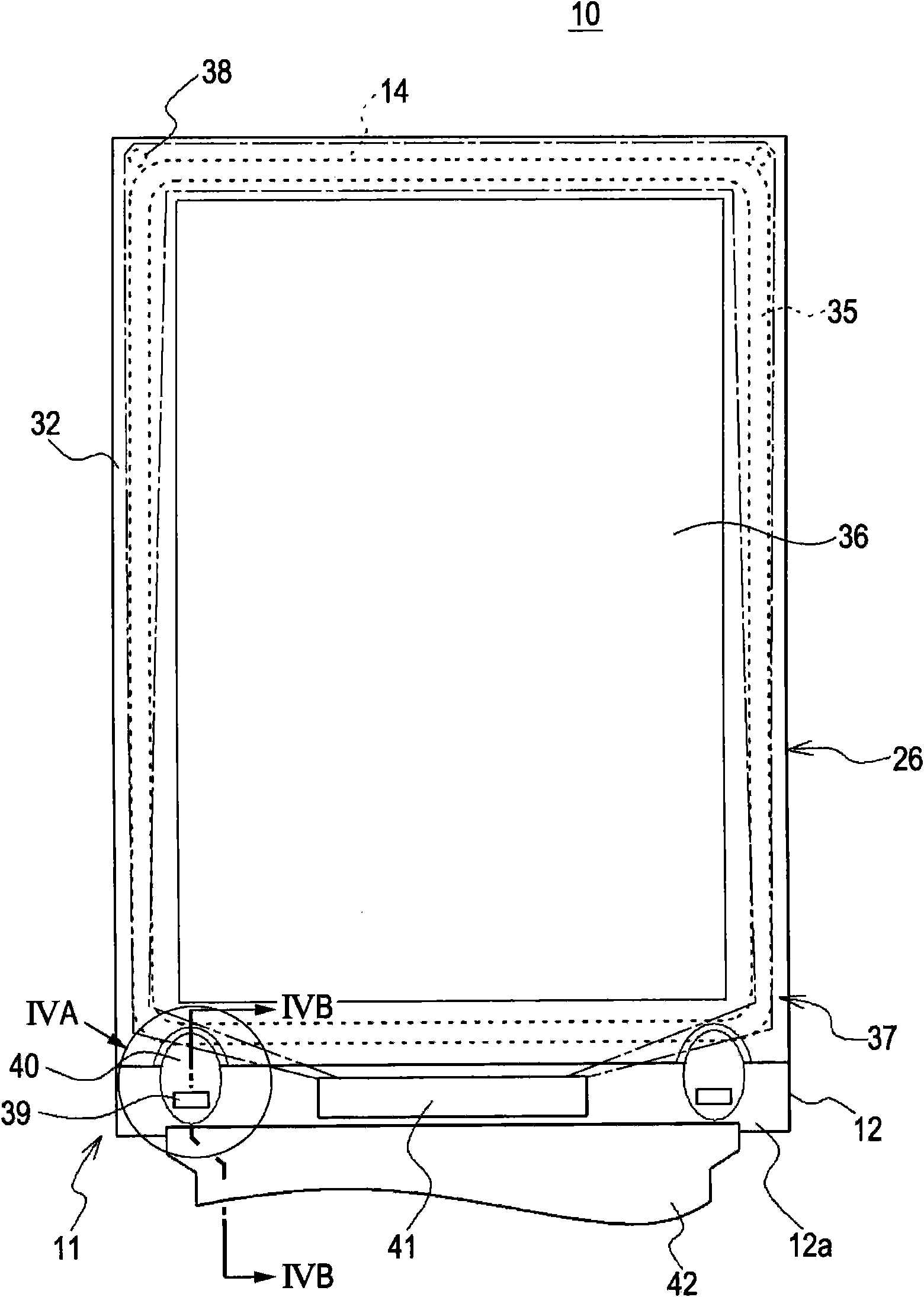
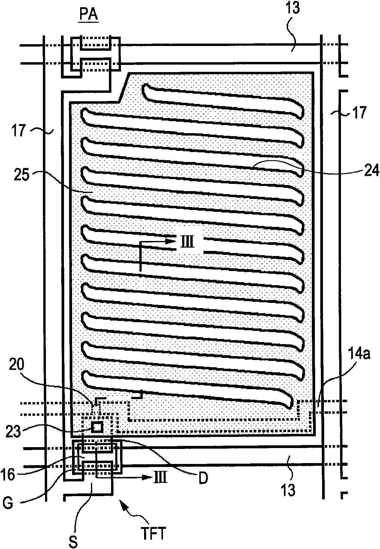
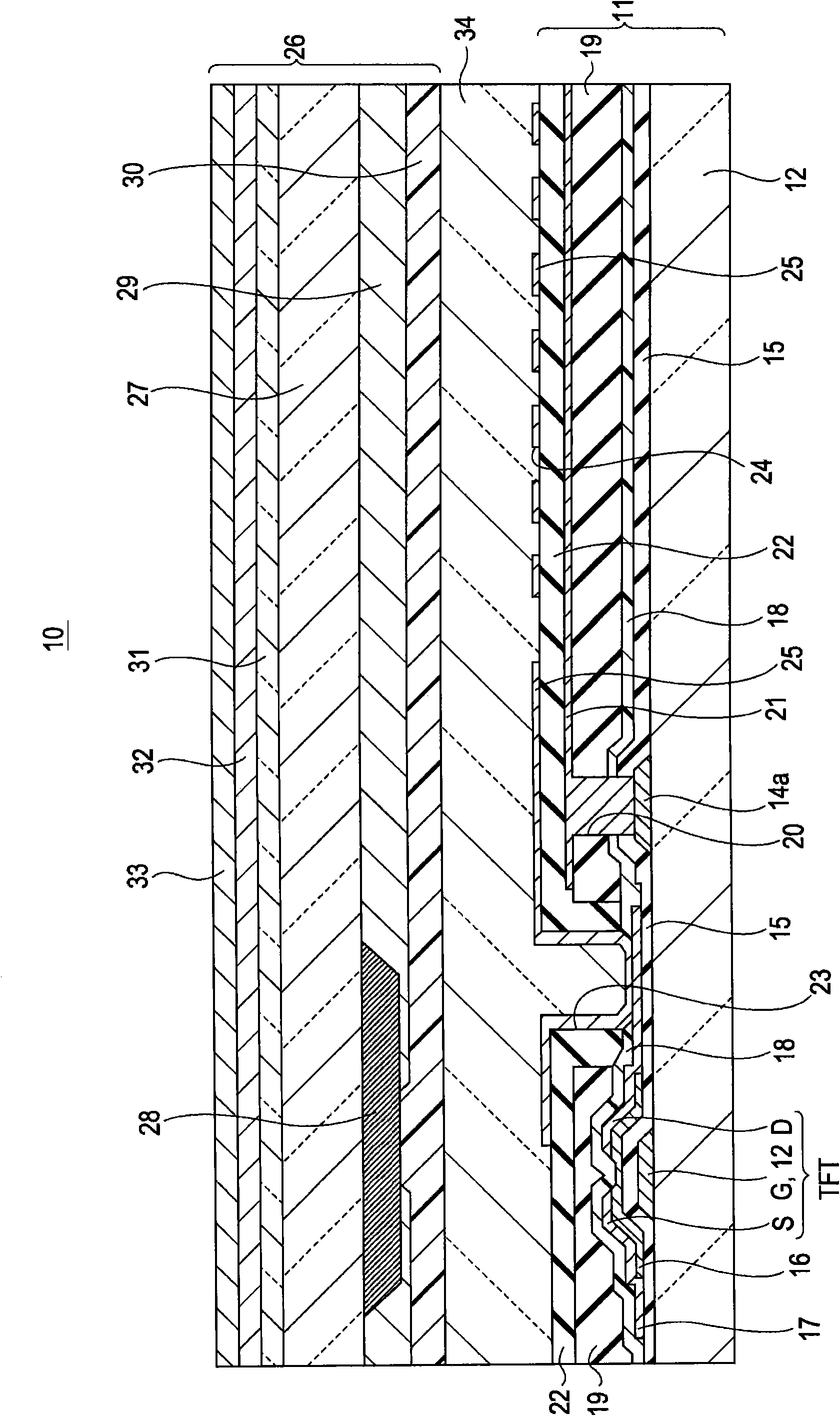
[0037] Below, will refer to Figures 1 to 4B The FFS mode liquid crystal display device 10 according to the first embodiment of the present invention will be described. refer to figure 1 , the liquid crystal display device 10 according to the first embodiment is a chip-on-glass (COG) type liquid crystal display device including an array substrate 11, a color filter substrate 26, a sealing material 35 for bonding the substrates 11 and 26 together, and a liquid crystal 34 ( refer to image 3 ), the liquid crystal 34 is contained in a region surrounded by the array substrate 11 , the color filter substrate 26 and the sealing material 35 . In the liquid crystal display device 10 , a display region 36 is formed in an inner region surrounded by the sealing material 35 . An area where no image is seen around the display area 36 is used as a non-display area 37 of the liquid crystal display device 10 . Since the liquid crystal display device 10 according to the first embodiment is...

no. 2 example

[0055] With the liquid crystal display device 10 according to the first embodiment, the case where the second conductive film is formed over the first conductive film except for the portion where the first conductive film is connected to the conductive paste has been described. In contrast, for the liquid crystal display device 10A according to the second embodiment, reference will be made to Figure 5 , 6A and 6B describe the case where not only the first conductive film but also the second conductive film is connected to the conductive paste. Since the liquid crystal display device 10A according to the second embodiment differs from the liquid crystal display device 10 according to the first embodiment only in the partial configuration of the second conductive film, the same parts as the liquid crystal display device 10 according to the first embodiment are used. The same reference numerals denote and simplify the detailed description of these components.

[0056] refer to...


PUM


Abstract

A horizontal-electric-field liquid crystal display apparatus is provided. A pair of substrates are bonded together through a sealing material. A liquid crystal is contained between the pair of substrates. A first electrode and a second electrode are formed on one of the pair of substrates. An electric field generated between the first electrode and the second electrode drives the liquid crystal. A first conductive film composed of a transparent conductive material is formed on a surface of another of the pair of substrates, the surface being opposite a surface in contact with the liquid crystal. The first conductive film is connected to a ground potential through a connection member composed of a conductive material. A second conductive film composed of a transparent conductive material is formed on a surface of the first conductive film. Also, a polarizing plate is formed on a surface of the second conductive film.

Description

technical field [0001] The invention relates to a horizontal electric field liquid crystal display device. In particular, the present invention relates to a horizontal electric field liquid crystal display device in which corrosion of a conductive film made of a conductive material and used as an electrostatic shield caused by acid generated from an adhesive for a polarizing plate is suppressed. Background technique [0002] The horizontal electric field liquid crystal display device has a configuration in which a pair of electrodes is provided on the inner surface side of one of a pair of substrates provided to sandwich a liquid crystal layer, and the pair of electrodes is electrically insulated from each other. One is, for example, an array substrate among the array substrate and the color filter substrate, and a substantially horizontal electric field is applied to the liquid crystal molecules. As such a horizontal electric field liquid crystal display device, there are ...

Claims


Application Information

Patent Timeline
Patent Type & Authority Patents(China)
IPC IPC(8): G02F1/1333G02F1/1335G02F1/1343G02F1/13
CPCG02F2001/133388G02F2001/134372G02F2202/22G02F1/134363G02F2001/133334G02F1/133334G02F1/133388G02F1/134372
Inventor 笕宪之介伊藤健二
Owner JAPAN DISPLAY INC
Learn More