
Mechanical and electrical integrated driving wheel system

A driving wheel, electromechanical technology, applied in the direction of wheels, electromechanical devices, electric components, etc., can solve the problems of unsuitable power performance and use environment of medium and heavy vehicles, large driving torque, etc., to improve system integration, high power density, The effect of increasing the driving torque

Inactive Publication Date: 2013-10-09
CHINA NORTH VEHICLE RES INST
View PDF6 Cites 0 Cited by
  • Summary
  • Abstract
  • Description
  • Claims
  • Application Information

AI Technical Summary

Problems solved by technology

[0002] At present, the electric wheels used for electric and hybrid vehicles at home and abroad are biased towards the development of small vehicles or super-large engineering vehicles, but they cannot be applied to the power performance and use environment requirements of conventional medium and heavy vehicles, including high-speed vehicles. Driving power, high drive torque, and mass and size interface restrictions

Method used


Image

  • Mechanical and electrical integrated driving wheel system
  • Mechanical and electrical integrated driving wheel system
  • Mechanical and electrical integrated driving wheel system

Examples


Embodiment 1

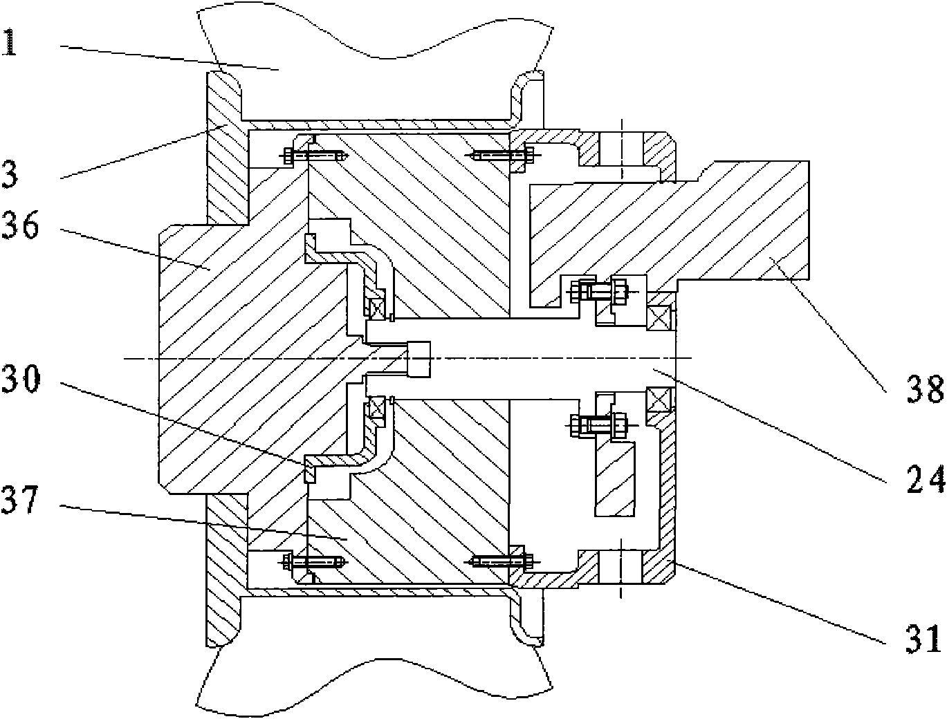
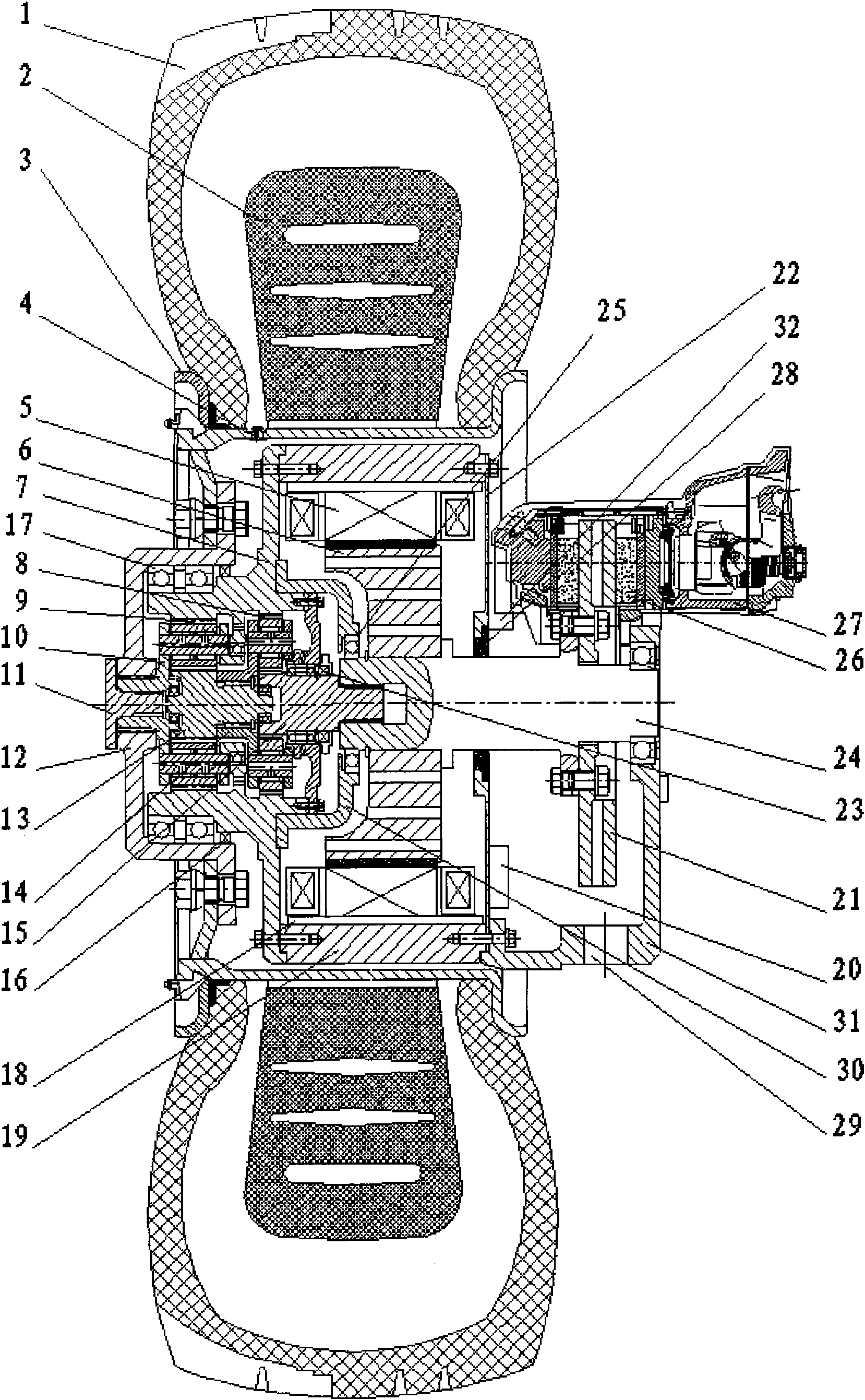
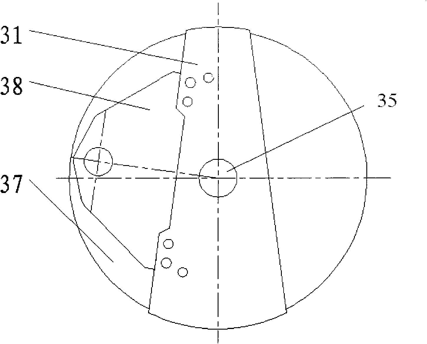
[0022] like figure 2 Shown is a new electromechanical integrated drive wheel system for pneumatic brakes of the invention, which is suitable for brakes with larger diameters and installed on different sides. The new electromechanical integrated driving wheel system includes a tire steel rim 3, tire rubber body 1, transmission main shaft 24 and braking device 38, and the transmission main shaft 24 of the driving wheel is connected with a driving motor system, a deceleration torque increasing system and a braking system. The device 38, and the drive motor device 37 and the deceleration and torque increasing device 36 are all integrated in the tire rim 3. The transmission main shaft 24 of this driving wheel has a cylindrical groove for the left end, has a cylinder structure of keyway in the cylindrical groove, and the middle part of transmission main shaft 24 is fixed with drive motor rotor 6. The motor stator silicon slice and the winding 5 are fixed on the drive motor housing...

Embodiment 2

[0031] This embodiment is suitable for brakes with smaller diameters and installed on the same side. The basic mechanism is similar to that of Embodiment 1, except that the brake device 38 adopts a hydraulic brake, and the installation position is slightly different. Figure 4 shown. In the present invention, the transmission main shaft 24 is the main component, the drive motor rotor 6 is fixed in the middle of the main shaft, the front end of the main shaft is connected with the primary planetary sun gear 15 to drive the sun gear through a spline connection, and the output power of the primary planetary frame 14 is connected with the secondary sun gear 13 connection, output power through the secondary planetary frame 10, and drive the tire steel ring 3 and the tire rubber body 1 to rotate partially. The first-stage planetary ring gear 8 and the second-stage planetary ring gear 9 are fixed in the reducer housing 7 and are fixed parts of the planetary reducer. The reducer hous...


PUM


Abstract

The invention provides a mechanical and electrical integrated driving wheel system, which comprises a tyre rim, tyre rubber, a transmission main shaft and a brake system, wherein the transmission main shaft of the driving wheel is connected with a driving motor system, a speed-reducing torque-increasing system and the brake system; and the driving motor system and the speed-reducing torque-increasing system are integrated in the tyre rim. The wheel changes the condition that only the brake system is arranged in the prior art; the driving motor system and the speed-reducing torque-increasing system are subjected to structural design in an uneven space, and the system integration level is improved; and the wheel has high power density and high universality, and meets the using requirements of most medium and heavy duty wheeled vehicles in China at present.

Description

technical field [0001] The invention belongs to the field of automobile wheel design, and in particular relates to a driving wheel system. Background technique [0002] At present, the electric wheels used for electric and hybrid vehicles at home and abroad are biased towards the development of small vehicles or super-large engineering vehicles, but they cannot be applied to the power performance and use environment requirements of conventional medium and heavy vehicles, including high-speed vehicles. Driving power, large drive torque, and quality and size interface restrictions. Contents of the invention [0003] The purpose of the present invention is to provide an electromechanical integrated driving wheel system, which satisfies the integration of key components such as driving motors, reducers and brakes at the present stage. [0004] The technical scheme that realizes the object of the present invention: [0005] An electromechanical integrated driving wheel system...

Claims


Application Information

Patent Timeline
Patent Type & Authority Patents(China)
IPC IPC(8): B60K7/00B60T1/06B60K17/04B60B19/00H02K7/10
Inventor 孟磊马亚青张鹤方青峰
Owner CHINA NORTH VEHICLE RES INST
Learn More