Method and control unit for operating transmission

A transmission and controller technology, which is applied in transportation and packaging, vehicle gearboxes, transmission control, etc., can solve problems such as the inability to accurately determine the position of claw teeth, and achieve the effect of low cost

Active Publication Date: 2020-06-09
ZF FRIEDRICHSHAFEN AG
View PDF5 Cites 0 Cited by
  • Summary
  • Abstract
  • Description
  • Claims
  • Application Information

AI Technical Summary

Problems solved by technology

[0015] Here the sensor signal values ​​have non-negligible deviations which lead to an inaccurate determination of the current claw position

Method used


Image

  • Method and control unit for operating transmission
  • Method and control unit for operating transmission
  • Method and control unit for operating transmission

Examples


Embodiment Construction

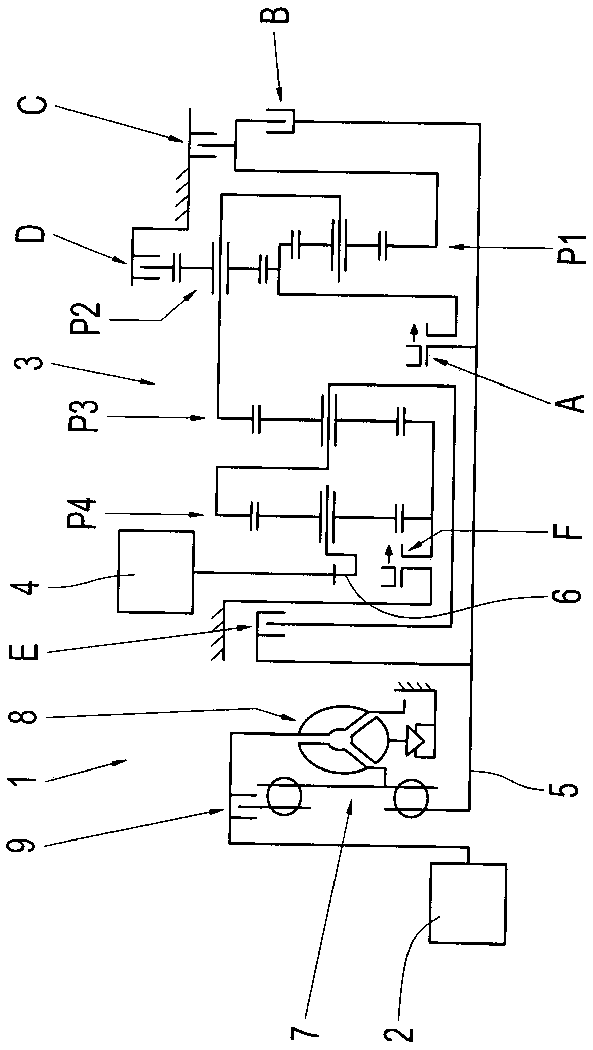
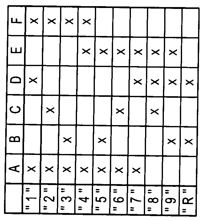
[0055] figure 1 A schematic diagram of a vehicle drive train 1 comprising a drive machine 2 , a transmission 3 and an output 4 is shown. Drive machine 2 is presently designed as an internal combustion engine. The transmission 3 is an automatic transmission in which a plurality of gear ratios "1" to "9" for forward travel and at least one gear ratio "R" for reverse travel can be realized. Depending on the corresponding configuration of the vehicle drive train 1 , the output 4 includes one, two or more drivable axles, which can be acted upon via the transmission 3 with the torque of the drive machine 2 . The hydraulically operable shift elements A to F are actuated during a transmission ratio change in the transmission 3 , ie during an upshift or a downshift in the transmission 3 . When the transmission ratio is changed, the traction force should be kept substantially uninterrupted, while at the same time having high driving comfort and the desired performance. The term "perf...


PUM


Abstract

A method for operating a transmission is provided, which includes a hydraulic pump drivable on a transmission-input end and at least one form-locking shift element. The shift element comprise two shift element halves that can be connected with each other in a locking mode. One of the shift-element halves is displaceable between a first end position and a second end position with a hydraulic pressure of the hydraulic pump. The end positions are corresponding to the closing operation state and the opening operation state of the shift element. The current position of the shift-element half is detected with a sensor and is stored as a specified end-position value if the shift-element half is located in one of the end positions, the hydraulic pump is driven, and the shift-element half is actuated, with the hydraulic pressure, towards the current end position. When the hydraulic pressure is less than a threshold value, a deviation is determined between the current position of the shift-element half and the specified end-position value. The hydraulic pressure is increased when the deviation is greater than a threshold value.

Description

technical field [0001] The invention relates to a method for operating a transmission of the type defined in detail in the preamble of patent claim 1 . Furthermore, the invention relates to a controller for carrying out the method and a corresponding computer program product. Background technique [0002] DE 10 2005 002 337 A1 discloses a transmission designed as an eight-speed multi-stage transmission, which has friction-locking shifting elements. The shifting elements are designed as disk clutches or disk brakes. When there is a shift request for changing the transmission ratio in the transmission, at least one frictional shifting element is disconnected from the power flow of the transmission device and at least another frictional shifting element is connected into the power flow of the transmission device , to transmit torque. [0003] In general, when the frictional shifting element is requested to be disengaged, it can be considered that the frictional shifting elem...

Claims


Application Information

Patent Timeline
Patent Type & Authority Applications(China)
IPC IPC(8): F16H61/02F16H63/42F16H61/40
CPCF16H61/0204F16H63/42F16H61/40F16H59/68F16H2059/6823F16H61/0025F16H61/686F16H61/0265F16H61/16F16H2200/0065F16H2710/20F16H2200/2046F16H2710/04F16H2708/20F16H2200/2012
Inventor M·耶勒A·施密特A·施维默C·潘内克D·泽劳特
Owner ZF FRIEDRICHSHAFEN AG
Why Eureka
Try Eureka