Laser scanning reader

A laser scanning and reader technology, used in optics, instruments, optical components, etc., can solve the problems of high cost, easy to fall, shock, etc., and achieve the effect of improving work stability and omitting settings.

Inactive Publication Date: 2011-05-04
PRIMAX ELECTRONICS LTD
View PDF1 Cites 4 Cited by
  • Summary
  • Abstract
  • Description
  • Claims
  • Application Information

AI Technical Summary

Problems solved by technology

However, the above-mentioned systems still require high-cost and complex optical-mechanical and electrical systems, and the optical-mechanical system and the electrical system are prone to drop and vibration problems. These are issues that must be overcome in the application of laser scanning

Method used


Image

  • Laser scanning reader
  • Laser scanning reader
  • Laser scanning reader

Examples


Embodiment Construction

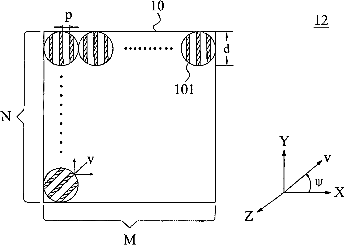
[0024] figure 1 It is a schematic plan view of the first preferred embodiment of the scanning beam generating module of the present invention. refer to figure 1 , a circular grating point matrix 10 is arranged on a plane 12, which includes an N*M two-dimensional matrix consisting of N rows and M columns (M, N are positive integers greater than 1) circular grating points 101, wherein M and N can be equal or different. The diameter of each circular grating point 101 is represented by d, and includes a plurality of parallel grating stripes; the distance between any two parallel grating stripes, or pitch (pitch), is represented by p, and v represents the distance from the grating The vector parallel to the stripes; the angle between the vector v of the parallel grating stripes and the X-axis of the X-Y plane where the plane 12 is located is called the azimuth angle ψ. In this embodiment, the size of the pitch p can cause diffraction phenomenon to light passing through the grati...


PUM


Abstract

The invention relates to a laser scanning reader which is used as a generator utilizing a round raster point matrix as a linear scanning beam, wherein the round raster point matrix is static when the linear scanning beam is generated for scanning. Compared with a common reader which needs a rotating mechanism to generate continuous scanning points as linear scanning lines, the laser scanning reader provided by the invention can reduce the cost of interior elements and simplify the configuration mode of the elements.

Description

technical field [0001] The invention relates to a scanning beam reading device, in particular to a laser scanning beam reading device. Background technique [0002] Laser scanning is a commonly used scanning technology, which is used in different products and fields, such as barcode readers, scanners, or laser range finders. Taking the barcode reader as an example, the basic principle is to scan the barcode by means of a scanning device, such as using a rotating scanning element to deflect and focus the laser beam into multiple parallel or cross scanning line patterns (scanning pattern) , to read the barcode on the item. After the signal reflected by the barcode is received, it can be judged, interpreted and managed after being processed by the electronic circuit and the decoder. [0003] The above-mentioned laser scanning systems generally require an opto-mechanical system combined with prisms and / or lenses to cooperate with a rotating device such as a motor system to obt...

Claims


Application Information

Patent Timeline
Patent Type & Authority Applications(China)
IPC IPC(8): G02B26/10G06K7/10
Inventor 王敬中
Owner PRIMAX ELECTRONICS LTD
Why Eureka
Try Eureka