
Remote online spectrum detection system

A spectrum detection and spectrum detector technology, applied in the field of online spectrum detection system, can solve the problems of unstable light energy transmission efficiency, short propagation distance of optical fiber probes, affecting coupling efficiency, etc., and achieve stable transmission efficiency, simple structure, and enhanced detection. effect of the signal

Inactive Publication Date: 2011-05-04
上海衡伟环保工程有限公司
View PDF4 Cites 7 Cited by
  • Summary
  • Abstract
  • Description
  • Claims
  • Application Information

AI Technical Summary

Problems solved by technology

However, when the optical fiber is bent, it will also lead to the instability of the light energy transmission efficiency and the decrease of the signal-to-noise ratio.
Therefore, the propagation distance of fiber optic probes currently on the market is generally relatively short.
In addition, when the current technology is used for absorbance detection, the traditional sample absorption cell adopts the coupling method of fiber collimator when coupling with the fiber. Various aberrations of the fiber collimator seriously affect the coupling efficiency, especially when When the spectral range is relatively wide, the aberration is large and the coupling efficiency is low, which makes the detection signal weaker and the detection lower limit rises

Method used


Image

  • Remote online spectrum detection system
  • Remote online spectrum detection system
  • Remote online spectrum detection system

Examples


Embodiment Construction

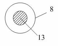
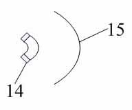
[0024] The following combination Figure 1 to Figure 4 , a preferred embodiment of the present invention is described in detail.

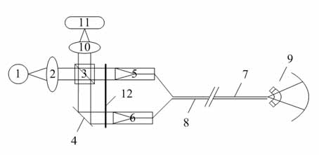
[0025] like figure 1 Shown is a schematic structural diagram of the remote online spectral detection system of the present invention. It includes: a light source assembly, a beam splitter 3 is arranged behind the light source assembly, a first detection optical path assembly, a second reference optical path assembly and a spectrum detection assembly are respectively arranged behind the beam splitter 3, and the An optical path chopper 12 is also arranged between the first detection optical path assembly and the second reference optical path assembly.

[0026] Wherein, the light source assembly includes a light source 1 and a first lens 2 arranged in sequence. The light source 1 can be a deuterium lamp, a tungsten halogen lamp, a xenon lamp, or any combination of the three, and the emission spectrum ranges from 900nm to 2500nm. In this embodiment...


PUM


Abstract

The invention discloses a remote online spectrum detection system. The system comprises a light source module, a beam splitter which is arranged behind the light source module, a first detection light path module, a second reference light path module, a spectrum detection module and a light path chopper, wherein the first detection light path module, the second reference light path module and thespectrum detection module are arranged behind the beam splitter respectively; the light path chopper is arranged between the first detection light path module and the second reference light path module; the first detection light path module comprises a first optical fiber collimating lens, a detection optical fiber core and a spherical sample cell sequentially; the second reference light path module comprises a planar mirror, a second optical fiber collimating lens and a reference optical fiber core sequentially, and metal silver is applied to the output end face of the reference optical fiber core; and the distance between the detection optical fiber core and the reference optical fiber core is in microndimension. The remote online spectrum detection system provided by the invention has high resolution, and stability, and is low in maintenance cost on the basis of realizing optical fiber long-distance transmission.

Description

technical field [0001] The invention relates to an on-line spectrum detection system, in particular to an on-line spectrum detection system which utilizes optical fiber technology to remotely separate photoelectric detection equipment from a sample pool, and belongs to the field of photoelectric detection. Background technique [0002] At present, most of the traditional analytical instruments can only work in the laboratory. Whether it is a spectral analysis instrument or a fluorescence detection instrument, there is a problem that the tested sample cannot be separated from the photoelectric detection equipment for a long distance, and it is not suitable for online detection in special occasions. , such as deep water detection, pipeline detection, cave detection and other special occasions, because these occasions are difficult for real-time sampling or access by large analytical instruments. Then, the use of optical fiber detection can play a very important and positive ro...

Claims


Application Information

Patent Timeline
Patent Type & Authority Applications(China)
IPC IPC(8): G01J3/28G01J3/02G08C23/06
Inventor 宋春立黄欣王勤华
Owner 上海衡伟环保工程有限公司
Learn More