
Permanent magnet mechanism automatic changeover switch

A technology of automatic transfer switch and permanent magnet mechanism, which is applied in the field of low-voltage electrical equipment and can solve the problems of high energy consumption, cumbersome structure of automatic transfer switch, and poor performance.

Active Publication Date: 2011-04-27
XI AN JIAOTONG UNIV
View PDF6 Cites 26 Cited by
  • Summary
  • Abstract
  • Description
  • Claims
  • Application Information

AI Technical Summary

Problems solved by technology

[0003] The purpose of the present invention is to solve the problems of the existing automatic transfer switch such as cumbersome structure, high energy consumption and poor performance, and provide a permanent magnet mechanism automatic transfer switch with simple structure, low energy consumption, phase separation operation and high reliability

Method used


Image

  • Permanent magnet mechanism automatic changeover switch
  • Permanent magnet mechanism automatic changeover switch
  • Permanent magnet mechanism automatic changeover switch

Examples


Embodiment Construction

[0017] specific implementation plan

[0018] The present invention will be described in further detail below in conjunction with the accompanying drawings.

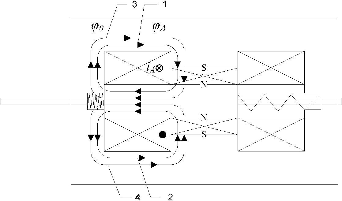
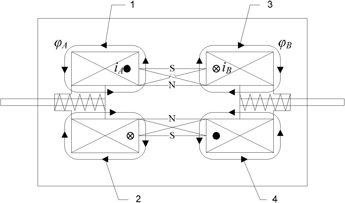
[0019] see figure 1 , the present invention includes a yoke 10 made of electrical pure iron material and a permanent magnet 14 made of NdFeB material arranged in the yoke 10, and a moving iron core made of electrical pure iron material is set inside the permanent magnet 14 13. In the yokes 10 on both sides of the permanent magnet 14, there are symmetrically arranged A combination gate coil 12 and B combination gate coil 15 wound by enamelled copper wires, and the two ends of the moving iron core 13 are respectively connected with the A combination gate coil made of stainless steel. One end of group A driving rod 9 and group B driving rod 17 is connected, and group A brake spring 11 and group B brake spring made of high carbon steel materials are respectively arranged on group A driving rod 9 and group B driving rod 17 1...


PUM


Abstract

The invention belongs to low voltage electrical equipment, and relates to an operation mechanism and an arc extinguish chamber structure of an automatic changeover switch, in particular to a permanent magnet mechanism automatic changeover switch. The permanent magnet mechanism automatic changeover switch comprises two groups of dynamic and static contacts and arc extinguish chambers, a set of permanent magnet mechanism, and corresponding driving connecting rods and conducting rods, and is characterized in that: the permanent magnet mechanism is provided with three stable working positions andcan realize changeover control over the three working states of the automatic changeover switch; when the two groups of contacts are closed respectively, a permanent magnet provides holding force; when the two groups of contacts are opened at the same time, two opening springs provide the holding force; and an electromagnetic coil is electrified to work only during state changeover, so that the electric energy consumption of an electromagnetic mechanism is greatly reduced. When a three-phase system is formed, every phase adopts independent mechanism control so as to realize phase-separated operation, and arc-free break can be realized by phase-selected control; and the operation mechanism has a few parts, a simple structure and high reliability.

Description

technical field [0001] The invention belongs to low-voltage electrical equipment, and relates to an operating mechanism and an arc-extinguishing chamber structure of an automatic transfer switch, in particular to a novel automatic transfer switch with a permanent magnet mechanism. Background technique [0002] Automatic transfer switching equipment (ATSE) is composed of one or several transfer switching equipment and other necessary electrical appliances, which are used to monitor the power circuit and automatically transfer one or several load circuits from one power source to another. Automatic transfer switch, also known as "dual power automatic transfer switch", "automatic transfer switch" or "dual power switch", is a low-voltage electrical appliance widely used in industry, in military industry, electric power, petroleum, telecommunications, transportation There are important applications in other industries. The application status of automatic transfer switch applianc...

Claims


Application Information

Patent Timeline
IPC IPC(8): H01H3/28H01H9/34
CPCH01H3/28H01H2300/018
Inventor 张国钢张怡耿英三张鹏飞陈维吴杰
Owner XI AN JIAOTONG UNIV
Learn More