
Joint

A technology of connecting rods and fixing seats, which is applied in the direction of joints, connections, manipulators, etc., and can solve problems such as difficult connection devices

Inactive Publication Date: 2011-04-20
HONG FU JIN PRECISION IND (SHENZHEN) CO LTD +1
View PDF3 Cites 9 Cited by
  • Summary
  • Abstract
  • Description
  • Claims
  • Application Information

AI Technical Summary

Problems solved by technology

However, when the surface morphology of the workpiece to be polished is relatively complex, it is often necessary for the driven element connected to the grinding equipment to have a swing and reset function relative to the active element. It is generally difficult for the existing connecting device to meet the above requirements

Method used


Image

  • Joint
  • Joint
  • Joint

Examples


Embodiment Construction

[0010] The joint of the present invention will be further described in detail with reference to the accompanying drawings and embodiments.

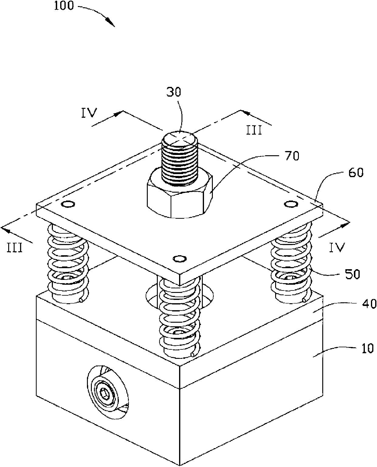
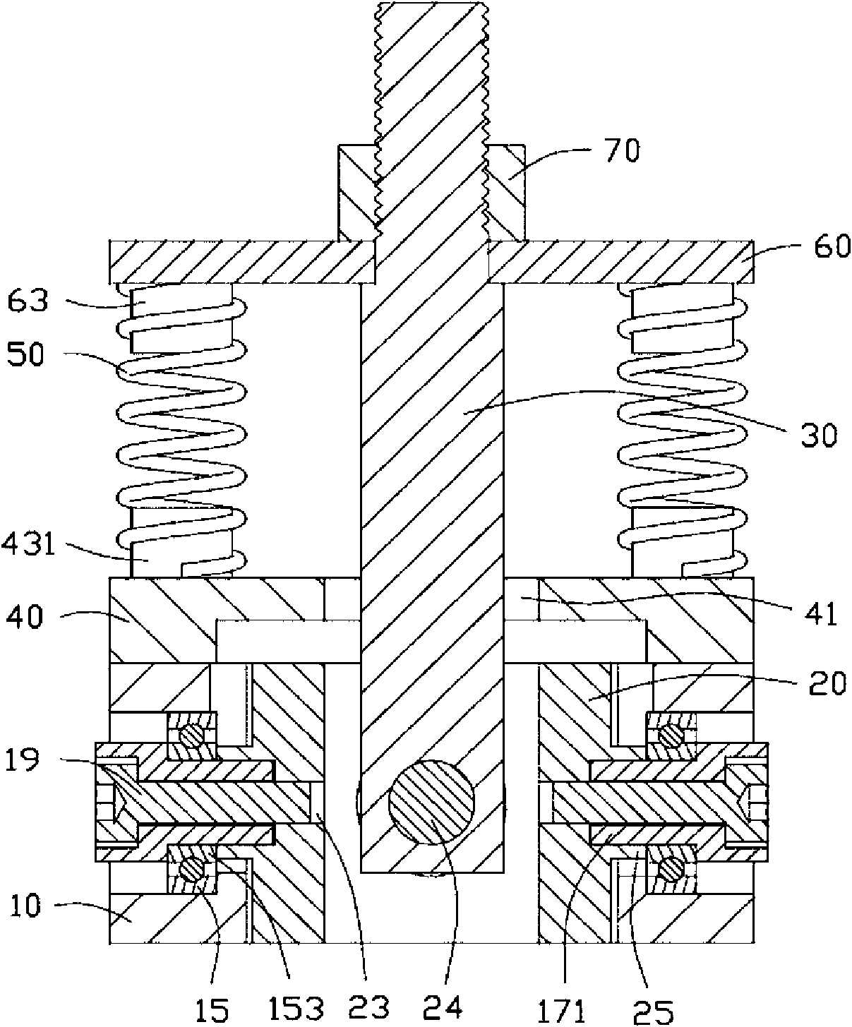
[0011] see figure 1 , the joint 100 of the embodiment of the present invention includes a fixing seat 10 , a connecting rod 30 , four elastic members 50 and a positioning plate 60 . The connecting rod 30 is movably connected with the fixed base 10 and can flexibly swing around relative to the fixed base 10 . The positioning plate 60 is sleeved on the connecting rod 30 , and the four elastic members 50 are disposed between the positioning plate 60 and the fixing seat 10 .

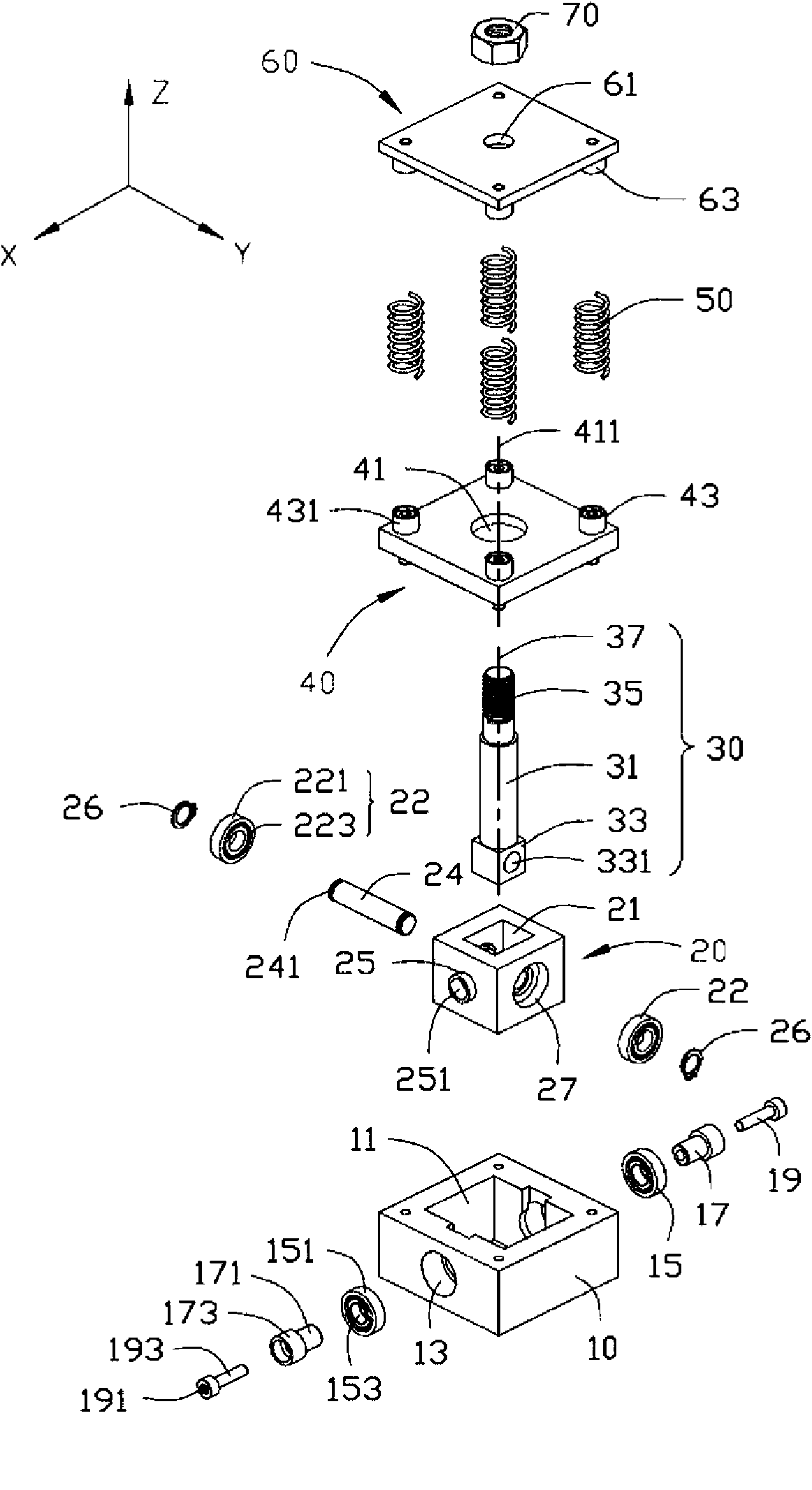
[0012] Please also see figure 2 , the fixing seat 10 is roughly a square block, and a square receiving cavity 11 is opened in the middle thereof. Two opposite side walls of the fixing base 10 along the X-axis as shown in the figure are respectively provided with an axis hole 13 communicating with the accommodating cavity 11 .

[0013] The joint 100 also includes tw...


PUM


Abstract

The invention relates to a joint which comprises a fixed seat, a connecting rod and at least two elastic elements, wherein one end of the connecting rod is movably connected with the fixed seat; the joint also comprises a positioning plate; the positioning plate is fixedly connected to the connecting rod; the at least two elastic elements are arranged between the fixed seat and the positioning plate and positioned at both sides of the connecting rod or surround the periphery of the connecting rod; and the connecting rod of the joint can be flexibly swung relative to the fixed seat and rapidly and accurately reset from the swinging position.

Description

technical field [0001] The invention relates to a joint, in particular to a swingable joint. Background technique [0002] With the development of industry, automation equipment has been widely used in various production fields, such as manipulators capable of grasping and moving, which can move according to the set trajectory, and cooperate with the grinding device to achieve grinding and polishing of the workpiece. The connection between the active element and the driven element of the existing manipulator mostly adopts a rigid fixed connection. However, when the surface morphology of the workpiece to be polished is relatively complex, it is often necessary for the driven element connected to the grinding equipment to have a swing and reset function relative to the active element. It is generally difficult for existing connecting devices to meet the above requirements. Contents of the invention [0003] In view of the above situation, it is necessary to provide a joint ...

Claims


Application Information

Patent Timeline
Patent Type & Authority Applications(China)
IPC IPC(8): B25J19/00
CPCB25J17/0208B25J17/0275Y10T403/75Y10T403/45
Inventor 宋尚轩张成
Owner HONG FU JIN PRECISION IND (SHENZHEN) CO LTD
Learn More