
Column type metal cutting machine

A metal cutting, column-type technology, applied in the field of machine tools, can solve the problems of complex overall structure, large space occupation, and high equipment cost, and achieve the effect of simple overall structure, reduced equipment cost, and small space occupation

Inactive Publication Date: 2011-04-20
DALIAN HUAGEN MACHINERY
View PDF10 Cites 4 Cited by
  • Summary
  • Abstract
  • Description
  • Claims
  • Application Information

AI Technical Summary

Problems solved by technology

The overall structure of the equipment with this structure is complex and takes up a lot of space. When choosing a cylinder, a large diameter cylinder is required, which is easy to slip during work, and a large capacity air storage container is required, and piping is required; when an oil cylinder is selected, a hydraulic unit and piping are required. Also has to deal with oil temperature rise in hydraulic circuit; high equipment cost

Method used


Image

  • Column type metal cutting machine
  • Column type metal cutting machine

Examples


Embodiment Construction

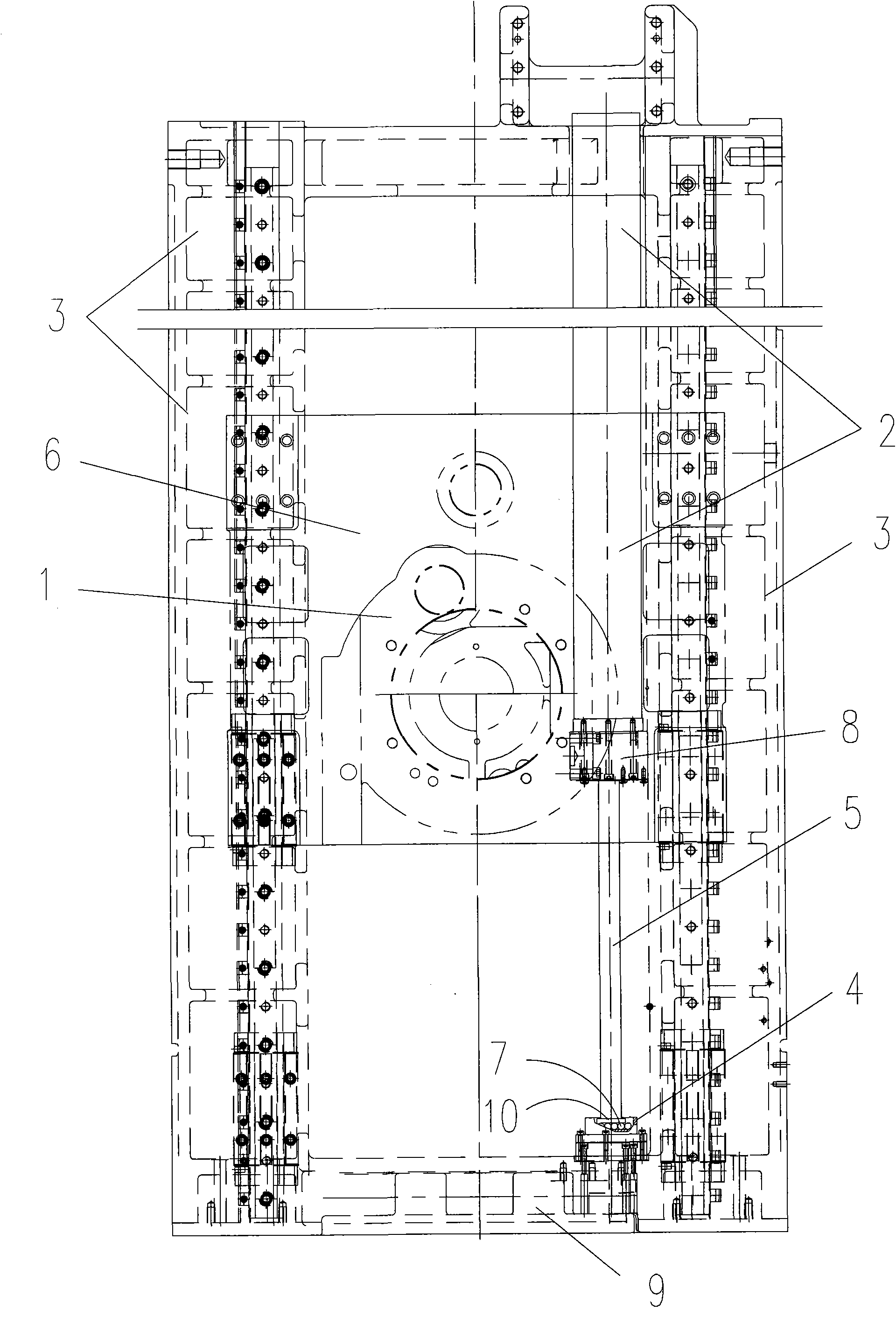
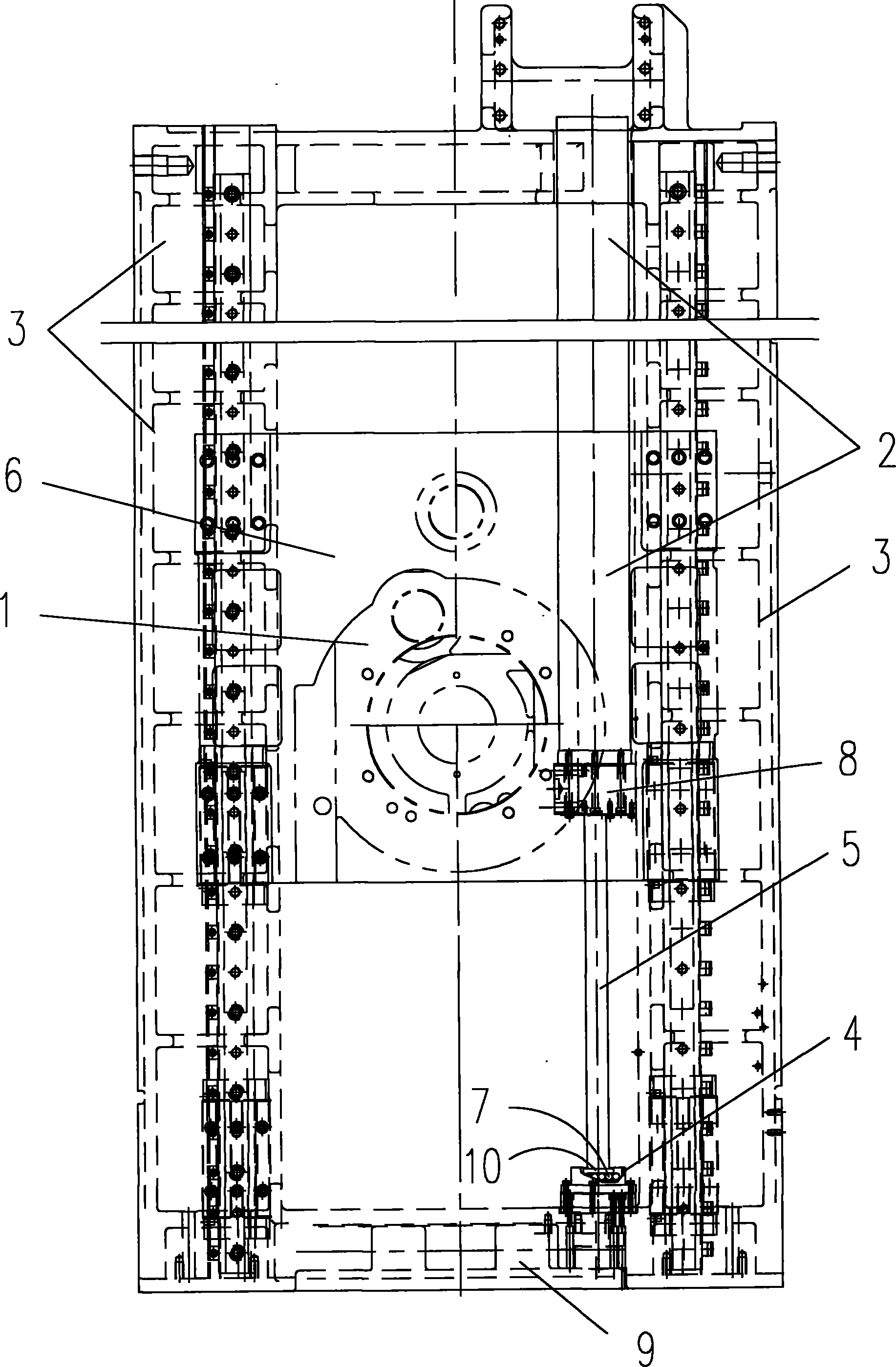
[0008] Such as figure 1 As shown: 3 is a box-type column, forming a frame structure, 6 is a slide plate, and the slideway is connected between the slide plate and the box-type column 3. The slideway can be a linear guide rail type or a dovetail groove structure, and the slideway is set in a vertical direction. , so that the slide plate 6 can move up and down relative to the box-type column 3 driven by the driving mechanism. A headstock 1 is installed on the slide plate 6 . Below the spindle box 1 there is a bed that is connected with the box-type column 3 as one, on the bed is installed a mobile workbench that is connected with the drive mechanism and fixes the workpiece.

[0009] 2 is the optional nitrogen balance cylinder. The lower end of the nitrogen balance cylinder 2 has a mounting seat 8, and the nitrogen balance cylinder 2 is fixedly installed on the box body of the headstock 1 or on the slide plate 6 through the mounting seat 8 and the fixing bolts. Make the nitroge...


PUM


Abstract

The invention discloses a column type metal cutting machine comprising a tank type column, a slideway is arranged on the tank type column vertically, the tank type column is connected with a sliding plate through the slideway, a main spindle box is installed on the sliding plate, and a moving bolster is arranged below a main shaft; a nitrogen compensating cylinder vertically arranged is installed on the main shaft box or the sliding plate; and the external end of the piston rod matched with the nitrogen compensating cylinder props against the bottom of the tank type column. Compared with the prior art, the metal cutting machine has the advantages of less components, simple overall structure, lowered equipment cost and small occupied space after installation.

Description

technical field [0001] The invention relates to a machine tool, in particular to a column type metal cutting machine tool. Background technique [0002] The existing column-type metal cutting machine tool has a box-type column, and a slideway is provided in the vertical direction on the box-type column. The slideway is usually a linear guide rail or a dovetail slideway, and a slide plate is connected through the slideway. The spindle box has a movable workbench for placing workpieces under the spindle. Due to the heavy weight of the skateboard and the headstock, in order to offset part of the gravity, at least two sets of pulleys are installed above the box-type column. The outer ends of the piston rods in the cylinder or oil cylinder are connected. A part of the gravity of the headstock and the slide plate can be counteracted by the air cylinder or the oil cylinder. The overall structure of the equipment with this structure is complex and takes up a lot of space. When ch...

Claims


Application Information

Patent Timeline
IPC IPC(8): B23Q1/01
Inventor 王世鹏高永强李凯王坤
Owner DALIAN HUAGEN MACHINERY
Learn More