
Method and device for combustion of solid fuel

一种燃料、燃烧器的技术,应用在燃烧方法、燃烧粉末燃料的燃烧器、燃烧的空气/燃料供给等方向,能够解决火焰温度高等问题

Inactive Publication Date: 2011-04-13
AGA AB
View PDF0 Cites 0 Cited by
  • Summary
  • Abstract
  • Description
  • Claims
  • Application Information

AI Technical Summary

Problems solved by technology

The problem with this type of combustion is that the flame temperature locally becomes very high

Method used


Image

  • Method and device for combustion of solid fuel
  • Method and device for combustion of solid fuel
  • Method and device for combustion of solid fuel

Examples


Embodiment Construction

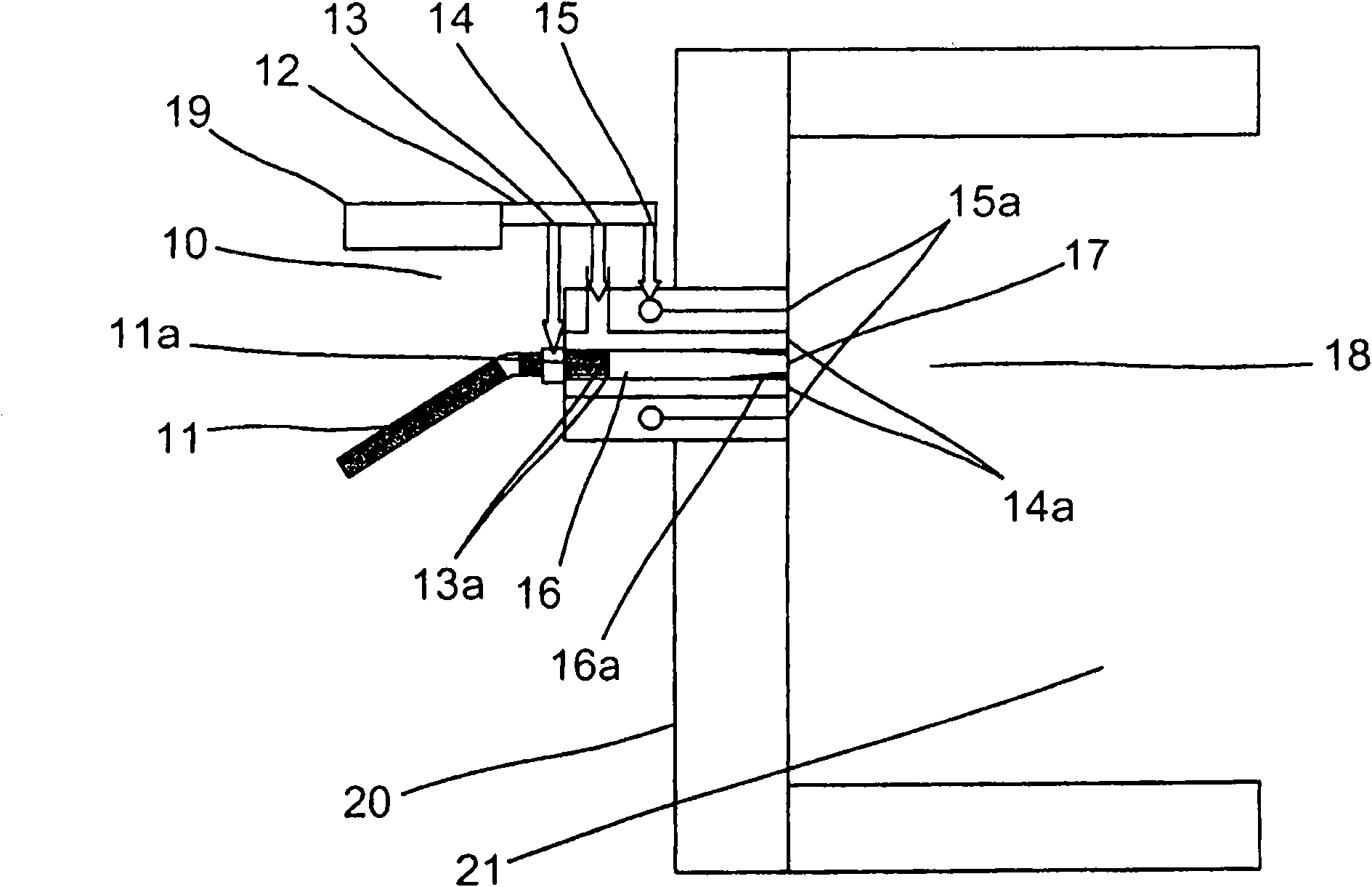
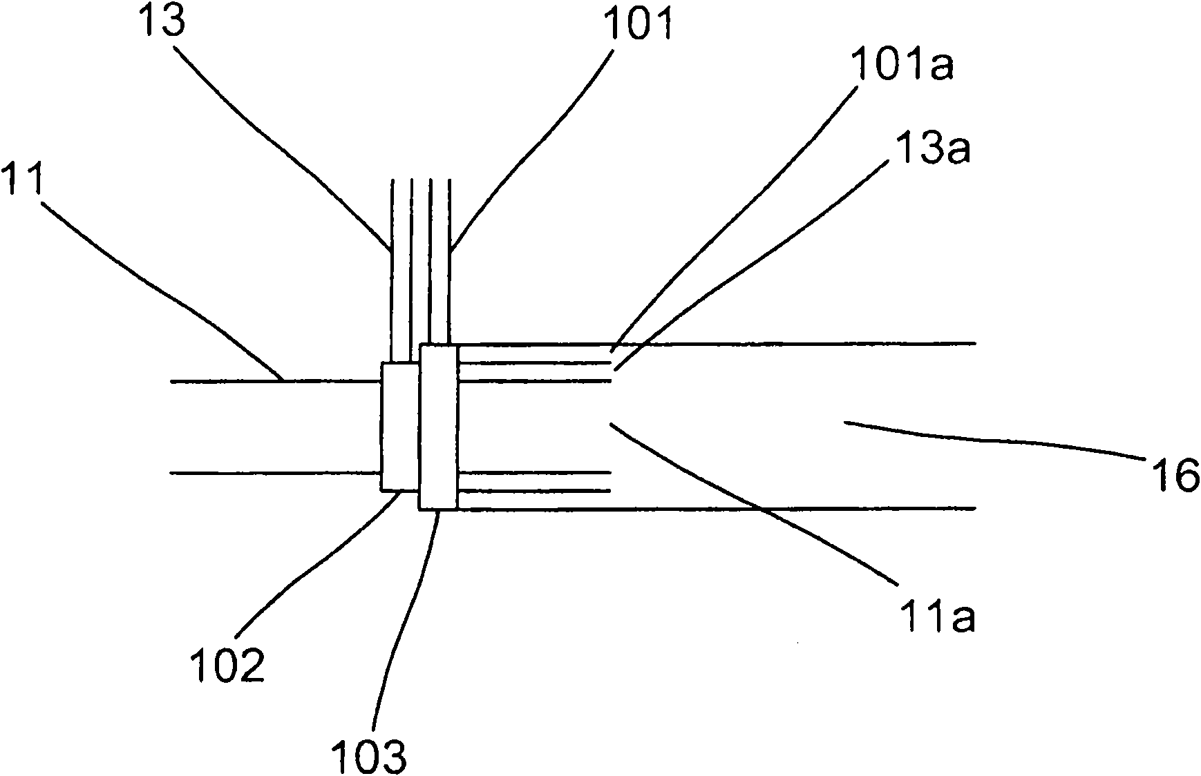
[0013] figure 1 A burner arrangement 10 according to the invention is shown which is suitable for carrying out the method according to the invention. The burner arrangement 10 is mounted on a furnace wall of an industrial furnace 20 and is oriented such that the combustion space 18 associated with the burner arrangement 10 is arranged within the heating space 21 of the furnace 20 . The industrial furnace 20 can be used to heat various materials such as glass, steel, non-ferrous metals, and ceramic materials. Furthermore, the burner arrangement according to the invention can also be used, for example, in heating plants, power stations or thermal power plants, where the heat from the burner arrangement 10 is used, for example, as municipal heating and / or converted into electricity.

[0014] A screw feeder or corresponding form of feeding means 11 is provided to feed a predetermined amount of solid phase fuel, such as pulverized coal, to the inlet port 11 a provided in the burne...


PUM


Abstract

Method for combusting a solid phase fuel, where the fuel is caused, by the help of a non-pneumatic feeding means (11), to be fed to an inlet opening (lla) in a burner device (10), where the burner device (10) is caused to comprise a first inlet (13a) for the oxidant through which an oxidant is caused to flow via a first supply conduit (13). The invention is characterised in that the first inlet (13a) for oxidant is caused to be arranged in the form of a first opening arranged by the inlet opening, through which the oxidant is caused to flow out, through a burner pipe (16) and out through a burner orifice (17) to a combustion space (18), so that the oxidant by ejector action causes the fuel to be conveyed through the burner pipe and out through the burner orifice (17), and in that water vapour is added to the oxi not dant before the oxidant reacts with the fuel.

Description

technical field [0001] The present invention relates to methods and apparatus for combusting solid phase fuels, and more particularly, the present invention relates to combustion within a burner apparatus using an oxidant having a high oxygen content. Background technique [0002] Typically when solid phase fuels are combusted in industrial burners, a pneumatic system is usually employed which includes a carrier gas for transporting the solid phase fuel from the inlet to the combustion space. For example, the fuel may be in the form of a powder such as pulverized coal, and may be propelled by the movement of a carrier gas. Typically, the carrier gas consists of air or nitrogen. Such combustion systems can be used, for example, to heat industrial furnaces. [0003] One problem with this approach is that the carrier gas constitutes a major part of the gas flow within the combustion device. Consequently, large amounts of ballast gas, for example in the form of nitrogen, have...

Claims


Application Information

Patent Timeline
Patent Type & Authority Applications(China)
IPC IPC(8): F23K3/02F23D1/00F23L7/00F23D14/78
CPCY02E20/342F23C2900/99001Y02E20/344F23C9/006F23L7/007F23L2900/07007F23D1/00F23L7/005Y02E20/34F23K3/00F23K3/02F23K2203/008
Inventor T·埃克曼A·卢内特
Owner AGA AB
Learn More