
Bone-conduction headphone

A bone conduction earphone and bone conduction speaker technology, applied in earphone/earphone accessories and other directions, can solve the problems of affecting sound purity, poor bass, discomfort, etc., and achieve the effect of eliminating the source of noise, fewer parts, and low cost

Inactive Publication Date: 2011-04-13
金在善
View PDF6 Cites 34 Cited by
  • Summary
  • Abstract
  • Description
  • Claims
  • Application Information

AI Technical Summary

Problems solved by technology

Although this kind of bone conduction earphone solves some problems of the earplug earphone, due to the limitations of the structure of the bone conduction earphone itself, when the volume of this earphone is slightly louder, it will be on the top of the three-claw elastic part. between the metal shrapnel, or between the metal shrapnel and the upper cover body, which affects the purity of the sound; in addition, the bass of this bone conduction earphone is not good, making people sound uncomfortable, especially when listening to music , the distortion is very serious

Method used


Image

  • Bone-conduction headphone
  • Bone-conduction headphone
  • Bone-conduction headphone

Examples


Embodiment 1

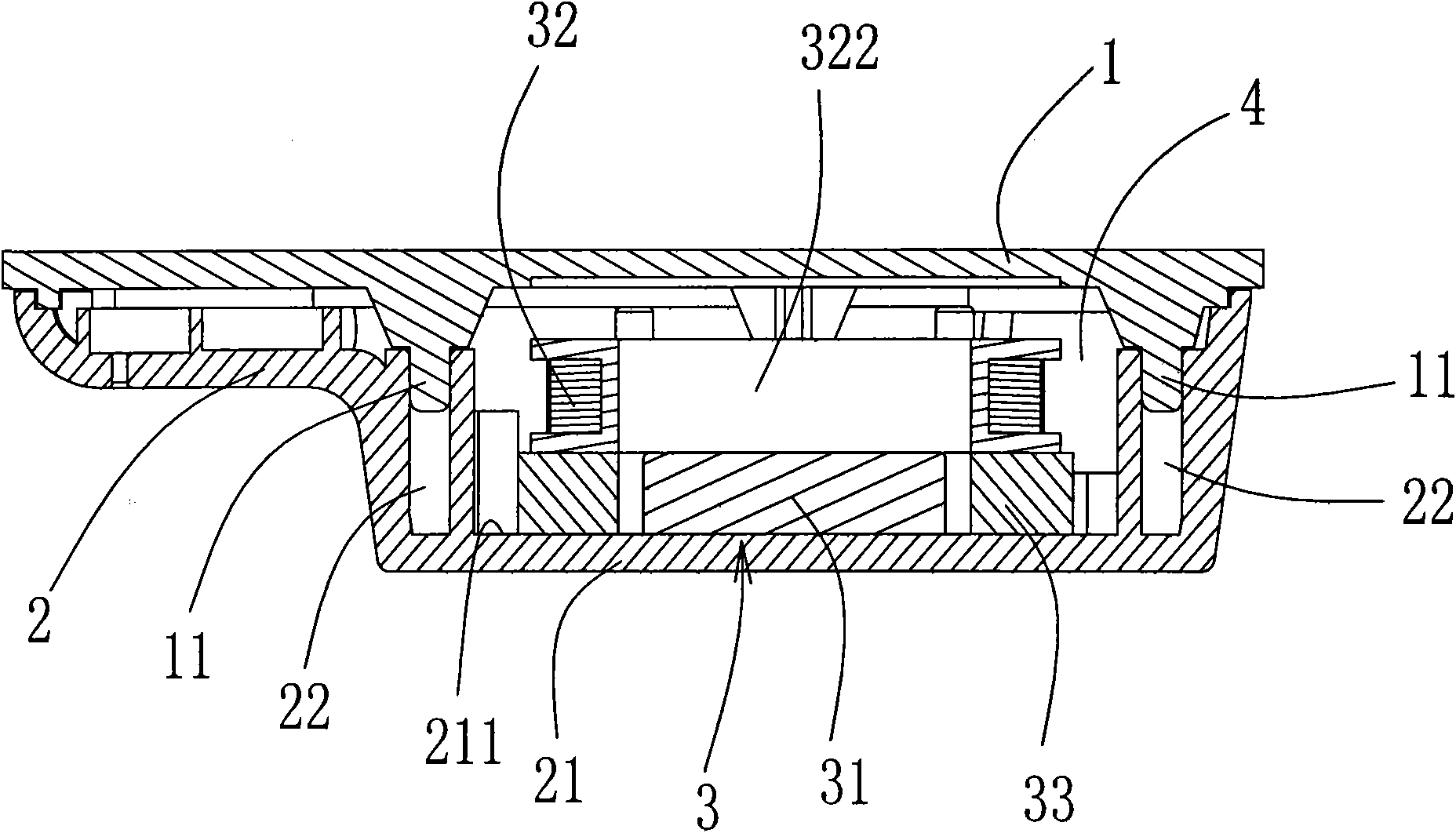
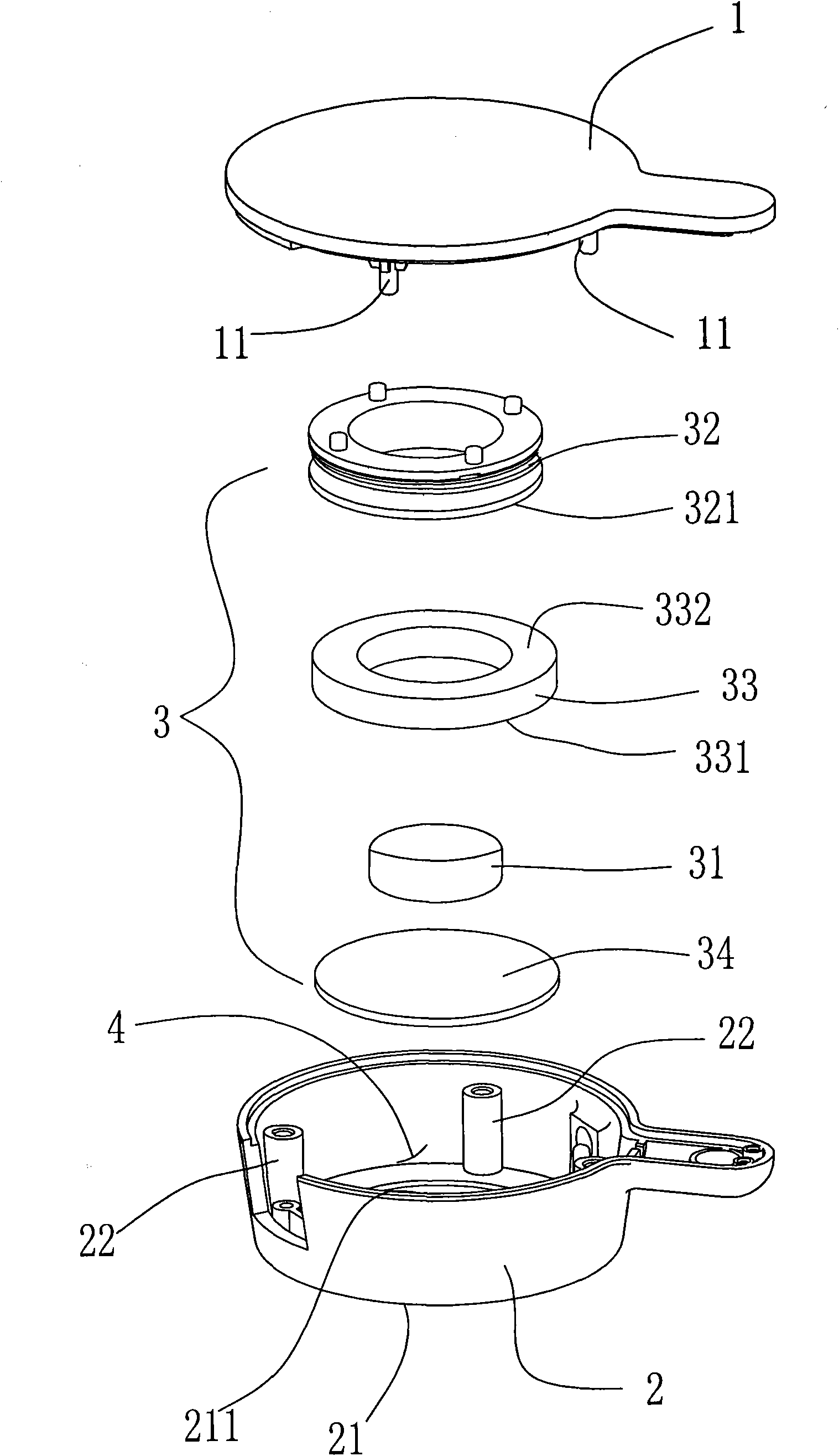
[0019] See figure 1 and figure 2 , figure 1 and figure 2 Disclosed is a bone conduction earphone, including an upper cover 1 and a lower cover 2 (that is, the cover part attached to the ossicle). After the upper cover 1 and the lower cover 2 are fastened together, they form a bone conduction speaker assembly The cavity 4 of 3 is provided with a bone conduction speaker assembly 3 in the cavity 4. The feature of the present invention is that the lower cover 2 is injection-molded at one time, and the lower cover 2 has a vibration plane 21. The traditional cover is composed of two parts into an integral structure, which can eradicate the noise caused by the weak bonding between the two parts. The vibration plane 21 in this embodiment is a circular surface, and the bone conduction speaker assembly 3 includes a magnet 31, a coil 32 and a buffer ring 33, the magnet 31 is fastened on the inner wall 211 of the vibration plane 21 of the lower cover 2, and no noise will be generated...

Embodiment 2

[0021] See image 3 and Figure 4 , image 3 and Figure 4 Disclosed is a second embodiment of the present invention, image 3 and Figure 4 The example shown with the figure 1 and figure 2 Compared with the shown embodiment, its general structure is the same, the difference is: a metal elastic piece 34 is also provided between the inner wall 211 of the vibration plane 21 of the lower cover 2 and the magnet 31, and the metal elastic piece 34 It is fixed on the inner wall 211 of the vibration plane 21, and the magnet 31 is fastened on the metal elastic piece 34. Such a design can also improve the vibration effect of the present invention.

[0022] In the above two embodiments, the buffer ring 33 is made of sponge, which is a sponge ring. Obviously, the buffer ring 33 can also be made of silica gel; or made of EVA material; or made of rubber, etc. Made of cushioning material.

[0023] In the above two embodiments, the magnet 31 is a cylindrical magnet; obviously, the ma...


PUM


Abstract

The invention relates to a bone-conduction headphone which comprises an upper cover (1) and a lower cover (2), wherein the upper cover (1) and the lower cover (2) can form a cavity (4) for containing a bone-conduction loudspeaker assembly (3) after closed; the bone-conduction loudspeaker assembly (3) is arranged in the cavity (4); the lower cover (2) is formed by one-step injection molding and is provided with a vibration plane (21); and the bone-conduction loudspeaker assembly (3) comprises a magnet (31), a coil (32) and a buffering ring (33), wherein the magnet (31) is fastened on the inner wall (211) of the vibration plane (21) of the lower cover (2), the buffering ring (33) is sheathed on the magnet (31) and is provided with the coil (32). The invention has the advantages of almost no noise, deep bass, simple structure and low cost.

Description

technical field [0001] The invention relates to a bone conduction earphone, in particular to a bone conduction earphone with small noise, rich bass and high volume. Background technique [0002] The traditional earphones are generally attached to or plugged in the ear holes. The earphones vibrate the air, and the air vibrates the eardrum of the person to transmit the sound to the human brain. This earplug type earphone, owing to need earphone to be attached to ear hole or be plugged in ear hole when using, like this, when people are listening to the sound in the earphone, the sound user of the outside world is difficult to hear, like this, when When encountering a dangerous situation, such as crossing the road, you can’t hear the whistle of the car, which is quite dangerous; in addition, if you use this kind of earphone at a high volume for a long time, it will affect the human eardrum and cause tinnitus , can seriously cause hearing loss. In order to solve the above probl...

Claims


Application Information

Patent Timeline
IPC IPC(8): H04R1/10
Inventor 金在善
Owner 金在善
Learn More