Light-emitting diode-based insulator leakage current fiber sensor system
A technology of light-emitting diodes and optical fiber sensors, applied in voltage/current isolation, measuring current/voltage, instruments, etc., can solve the problems of monitoring instruments with very high precision requirements, being easily affected by surrounding magnetic fields, and poor electromagnetic anti-interference ability. , to achieve the effect of easy on-site installation and disassembly, avoiding the process of electromagnetic conversion, and improving sensitivity and accuracy
- Summary
- Abstract
- Description
- Claims
- Application Information
AI Technical Summary
Problems solved by technology
Method used
Image
Examples
Embodiment 1
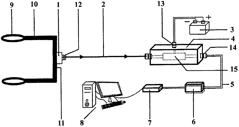
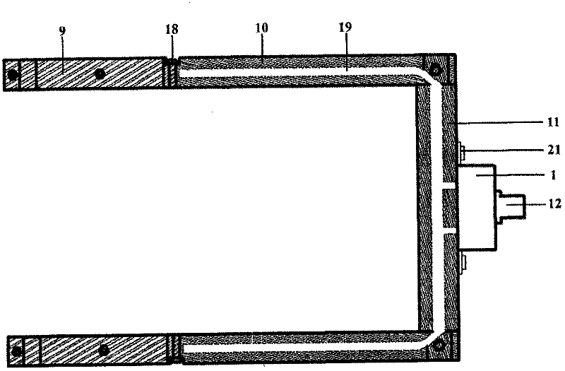
[0045] Such as Figure 1~4 As shown, a light-emitting diode-based insulator leakage current optical fiber sensor system mainly includes a fixed bracket, a sensor probe 1, an optical fiber 2, a photoelectric converter 4, a signal modulator 6, a data acquisition card 7, and a computer 8. The fixed support is an open clamp-shaped support composed of two open rings 9 and a probe support. The two open rings 9 are made of brass, and each open ring 9 is formed by two half rings interlocking. The inner diameter of each open ring 9 is 80 mm, the outer diameter is 90 mm, and the thickness is 10 mm. The two open rings 9 are respectively clamped on the steel caps of the adjacent insulators of the tested insulator string 23 on the overhead line tower 22. to monitor the leakage current flowing through the insulator string 23. Screw holes are respectively provided at the opening and the middle of the semi-circle of each split ring 9, and the split ring 9 is fixedly connected to the steel c...
Embodiment 2
[0053] A kind of insulator leakage current optical fiber sensor system based on light-emitting diode, with embodiment 1, wherein: the inner diameter of two open rings 9 is 82mm, the outer diameter is 92mm, the thickness of ring is 13mm; The cross arm 10 length of probe holder is 290mm, the length of the longitudinal arm 11 is 147mm, the length of the rectangular section of the hollow transverse arm 10 and the longitudinal arm 11 is 26mm, and the width is 20mm; the diameter of the hollow channel 19 in the hollow transverse arm 10 and the longitudinal arm 11 is 5.5mm; the sensor probe 1 The housing of the housing is 33mm long, 26mm wide, 22mm high, and has a wall thickness of 1.5mm, and the epoxy resin coating thickness of the outer shell is 0.1mm; the housing of the photoelectric converter 4 has a length of 39mm, a width of 25mm, and a height of 21mm , The wall thickness is 1.5mm. The sensitivity to detect leakage current is 39.8mV / mA.
Embodiment 3
[0055] A kind of insulator leakage current optical fiber sensor system based on light-emitting diode, with embodiment 1, wherein: the inner diameter of two open rings 9 is 76mm, and outer diameter is 86mm, and the thickness of ring is 15mm; The cross arm 10 length of probe holder is 280mm, the length of the longitudinal arm 11 is 152mm, the length of the rectangular section of the hollow transverse arm 10 and the longitudinal arm 11 is 24mm, and the width is 22mm; the diameter of the hollow channel 19 in the hollow transverse arm 10 and the longitudinal arm 11 is 6.5mm; the sensor probe 1 The housing of the housing is 32mm long, 24mm wide, 24mm high, and has a wall thickness of 2.5mm. The thickness of the epoxy resin coating on the outer shell is 1mm; the housing of the photoelectric converter 4 has a length of 40mm, a width of 24mm, and a height of 20mm. The thickness is 2.5mm. The sensitivity to detect leakage current is 40.2mV / mA.
PUM
 Abstract
Description
Claims
Application Information
 - R&D
- Intellectual Property
- Life Sciences
- Materials
- Tech Scout
- Unparalleled Data Quality
- Higher Quality Content
- 60% Fewer Hallucinations
Browse by: Latest US Patents, China's latest patents, Technical Efficacy Thesaurus, Application Domain, Technology Topic, Popular Technical Reports.
© 2025 PatSnap. All rights reserved.Legal|Privacy policy|Modern Slavery Act Transparency Statement|Sitemap|About US| Contact US: help@patsnap.com


