
Novel key groove for back-upper heightening of stone-laying gravity dam

A gravity dam and masonry technology, applied in gravity dams, dams, etc., can solve the problems of tensile stress in new concrete, time-consuming and labor-intensive construction, etc., and achieve the effects of improving temperature stress, overcoming difficult procedures, and strong shear resistance

Active Publication Date: 2011-04-13
广东省水利电力勘测设计研究院有限公司
View PDF3 Cites 6 Cited by
  • Summary
  • Abstract
  • Description
  • Claims
  • Application Information

AI Technical Summary

Problems solved by technology

[0004] However, there are the following problems in the method of integral heightening of the rear foundation: due to the effect of concrete temperature stress, the new concrete poured on the downstream side of the old dam will shrink when it is cooled to a stable temperature, and this shrinkage is affected by the old dam and bedrock. As a result, the new concrete along the joint surface of the old dam body will generate tensile stress
Because it is required not to cause damage to the old dam, the above demolition methods are all done manually, and all loose rocks will be removed. The construction is obviously time-consuming and laborious.

Method used


Image

  • Novel key groove for back-upper heightening of stone-laying gravity dam
  • Novel key groove for back-upper heightening of stone-laying gravity dam
  • Novel key groove for back-upper heightening of stone-laying gravity dam

Examples


Embodiment 1

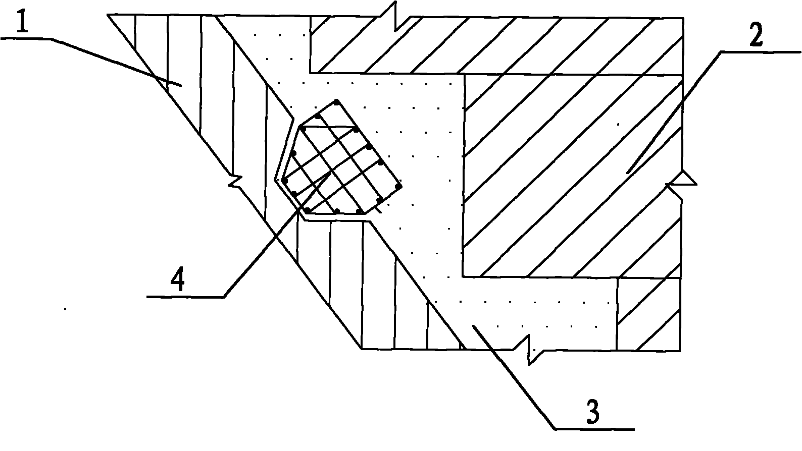
[0018] (1) Embed several shear keys in the original retaining dam section, of which a part of the shear key is buried in the original retaining dam section, and the other part is exposed;

[0019] (2) Simultaneously bury the pre-buried drainage pipe vertically and layeredly in the original retaining dam section; (DN100 soft permeable pipe can be preferably used), which can discharge the seepage water from the original retaining dam section out of the dam body.

[0020] (3) Heightening the retaining dam section, a backfill cavity is formed between the original retaining dam section and its heightened part, so the exposed part of the shear key falls into the backfill cavity, and the drain pipe falls into the The joint surface between the original retaining dam section and the backfill cavity;

[0021] (4) Fill the micro-expansion concrete into the backfill cavity.

Embodiment 2

[0023] The operation of this embodiment is basically the same as that of Embodiment 1, but in this embodiment, the backfill cavity is set in several steps, wherein each step is 2m high and 50cm-200cm wide.

Embodiment 3

[0025] The operation of this embodiment is basically the same as that of Embodiment 1, but in this embodiment, the shear keys are arranged horizontally in rows at fixed vertical intervals. Wherein the longitudinal section of the part of the shear key embedded in the original retaining dam section is set to be trapezoidal, and the longitudinal section of the part embedded in the backfill cavity is set to be rectangular.


PUM


Abstract

The invention provides a reinforced key groove for back-upper heightening of a stone-laying gravity dam and relates to a novel key groove in a hydro-structure. The key groove for the back-upper heightening of the stone-laying gravity dam is characterized in that before being heightened, the original water-retaining dam sections are heightened, a plurality of shear keys are buried in the orginal water-retaining dam sections, wherein one parts of shear keys are buried in the original water-retaining dam sections, and the other parts of shear keys are exposed, and then the dam is heightened. When the dam is heightened, a backfill cavity is formed between the original water-retaining dam sections and the heightened parts thereof so that the exposed parts of the shear keys drop in the backfill cavity, and finally micro-expansive concrete is filled in the backfill cavity finally. The novel key groove overcomes the adverse influences caused by the initial hydration heat of concrete as well as the defect of the difficult process of digging steps on original dams so that the dams are convenient to rapidly construct, and simultaneously also improves the temperature stress of newly cast large-size concrete so that the joint surface between a new dam body and an old dam body has stronger shearing resistance.

Description

【Technical field】 [0001] The invention relates to a novel reinforced keyway used in raising the height of a masonry gravity dam in a water conservancy project. 【Background technique】 [0002] There are many reasons for the heightening of the masonry gravity dam, such as the high cost of the original design and insufficient funds, so the heightening is done in stages to save the investment in the first phase of the project and make the project more effective in advance. Due to the increasing power load, the dam had to be heightened and the unit output increased to meet various requirements. However, the siltation of the reservoir is serious, and the storage capacity needs to be expanded so that the reservoir can continue to play its role and the hub will not be scrapped. The old dam should be raised to meet this requirement. Some dams lack sufficient data during design, resulting in insufficient dam height and storage capacity, which cannot meet the requirements of flood con...

Claims


Application Information

Patent Timeline
IPC IPC(8): E02B7/10
Inventor 董良山李贤锋
Owner 广东省水利电力勘测设计研究院有限公司
Learn More