
Gold plating solution for plating gold finger on circuit board

A gold finger and gold electroplating technology, applied in the field of electroplating, can solve the problems of poor electrical performance, anti-corrosion performance and welding performance, easy gold discoloration, uneven thickness, etc., to promote uniform catalytic nucleation, smooth coating, Mitigating the effect of plating pinholes

Inactive Publication Date: 2011-04-13
秦雅军
View PDF0 Cites 12 Cited by
  • Summary
  • Abstract
  • Description
  • Claims
  • Application Information

AI Technical Summary

Problems solved by technology

To make the plated gold fingers have good electrical properties, anti-corrosion properties and welding properties, on the one hand, the coating should not be too thick, because the cost is too high if it is too thick, and on the other hand, the electrical properties, anti-corrosion properties and welding properties are not good. Very good; on the other hand, the coating should not be too thin, on the one hand, it will easily cause gold discoloration after electroplating, on the other hand, its electrical performance, anti-corrosion performance and welding performance are not very good
[0003] In the circuit board industry, electroplating is generally used to plate gold fingers. The electrical performance, anti-corrosion performance and welding performance of electroplating are better than electroless plating. Therefore, the thickness is uneven, and gold plating is easy to discolor

Method used


Image

  • Gold plating solution for plating gold finger on circuit board
  • Gold plating solution for plating gold finger on circuit board

Examples


Embodiment 1

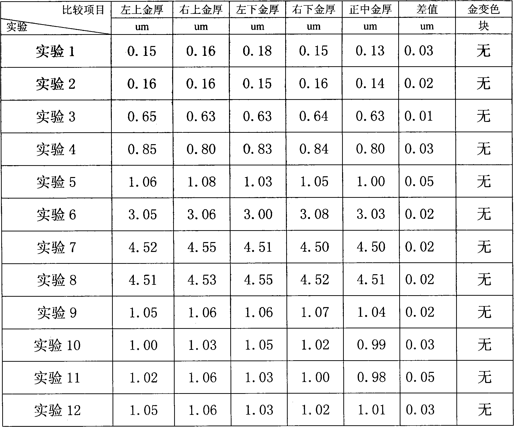
[0019] Prepare the electroplating gold solution 1 in the circuit board electroplating gold finger gold cylinder, take 20 pieces of the circuit board after conventional process operation to nickel plating, then carry out acid leaching in a conventional manner, then enter the gold cylinder containing electroplating gold solution 1, and turn on the power , after electroplating in a gold tank for 5 minutes, take it out, wash it with regular water, and dry it.

[0020] Cut out the upper left edge point (abbreviated as upper left), upper right edge point (abbreviated as upper right), lower left edge point (abbreviated as lower left), lower right edge point (abbreviated as lower right) and gold-plated layer in the middle (abbreviated as lower right) of each drying circuit board. The circuit board, along the thickness direction. Slice the excised material to observe the thickness of the gold plating, and observe the discoloration of the gold after leaving the uncut circuit board for 1...

Embodiment 2

[0024] Except that the electroplating gold solution is different, other is the same as embodiment 1.

[0025] Electroplating gold solution 2 is: gold content 1g / l (potassium gold cyanide), conductive salt 0.05g / l (citrate), metallic luster 0.05g / l (CuMn 2 o 4 ), organic gloss agent 0.05g / l (2,3-diaminopyridine), wetting agent 0.05g / l (sodium lauryl sulfate), appropriate amount of compounding agent (EDTA), appropriate amount of buffer solution, and the balance is water .

Embodiment 3

[0027] Except that the electroplating gold solution is different, other is the same as embodiment 1.

[0028] Electroplating gold solution 3 is: gold content 4.8g / l (potassium gold cyanide), conductive salt 0.1g / l (citrate), metallic luster 0.1g / l (CuMn 2 o 4 ), organic gloss agent 0.1g / l (2,3-diaminopyridine), wetting agent 0.1g / l (sodium lauryl sulfate), appropriate amount of compounding agent (EDTA), appropriate amount of buffer solution, and the balance is water .


PUM


Abstract

The invention discloses a gold plating solution for plating a gold finger on a circuit board, belonging to the filed of plating. The gold plating solution comprises gold salt the gold content of which is 1g / l to 30g / l, conductive salt, buffer solution, compounding agent, metallic brightener, organic brightener and wetting agent. The gold finger plated by the gold plating solution disclosed by the invention has the advantages of even and compact clad layer and gold solution conservation, and the plated gold is not easy to change color.

Description

technical field [0001] The invention relates to electroplating, in particular to an electroplating gold solution for plating circuit board gold fingers. Background technique [0002] Gold-plated film has good electrical performance, anti-corrosion performance and welding performance, so it is widely used on circuit boards. Some parts of the circuit board, such as the golden finger, must be plated with gold on its surface to ensure its good electrical performance and soldering performance. To make the plated gold fingers have good electrical properties, anti-corrosion properties and welding properties, etc., on the one hand, the coating should not be too thick, because the cost is too high on the one hand if it is too thick, and on the other hand, the electrical properties, anti-corrosion properties and welding properties are not good. Too good; on the other hand, the coating should not be too thin, on the one hand, it will easily cause gold discoloration after electroplatin...

Claims


Application Information

Patent Timeline
IPC IPC(8): C25D3/48
Inventor 秦雅军
Owner 秦雅军
Learn More