Vacuum photoconductive molecular/atomic gas micro-injection device

A technology of atomic gas and micro-spraying, which is applied in vacuum evaporation coating, molten spraying, sputtering coating, etc., can solve the problems of waste of materials, difficulty in precise control of injection materials, difficulty in grasping the range of action of jet/vapor, etc., to achieve The effect of reducing the process, saving materials, and simple structure

Inactive Publication Date: 2011-04-13
SHANGHAI UNIV
View PDF3 Cites 0 Cited by
  • Summary
  • Abstract
  • Description
  • Claims
  • Application Information

AI Technical Summary

Problems solved by technology

Both have a common problem in the atomization technology, that is, whether it is injection molding or vacuum thermal evaporation, it is difficult to grasp the range of action of the jet / vapour, which will cause difficulties in precise control of the injection material, and also cause material damage. waste

Method used


Image

  • Vacuum photoconductive molecular/atomic gas micro-injection device
  • Vacuum photoconductive molecular/atomic gas micro-injection device
  • Vacuum photoconductive molecular/atomic gas micro-injection device

Examples


Embodiment 1

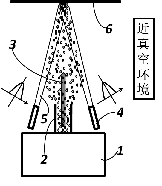
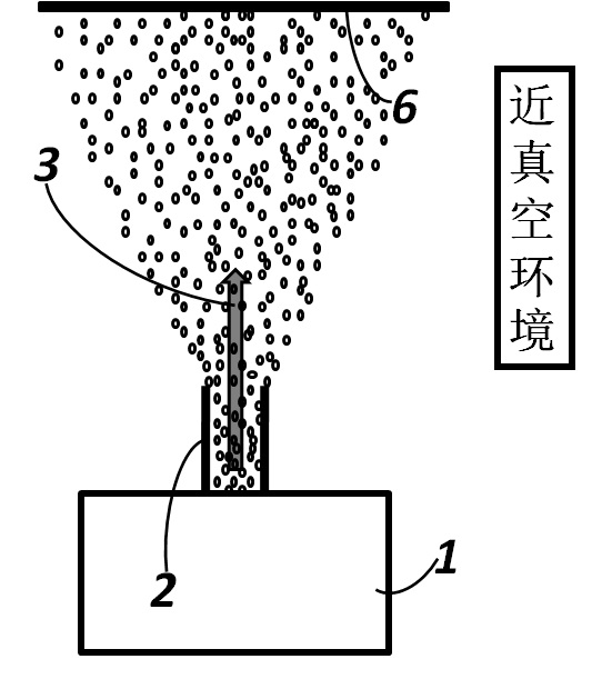
[0037] Embodiment one: see figure 1 , The vacuum photoconductive molecular / atomic gas micro-injection device is composed of a gas source 1, a spray nozzle 2, and a guiding light source 4. The device works in a near-vacuum environment, and the environmental pressure should be kept below 0.3 atmospheric pressure. The gas source 1 is connected to the injection nozzle 2 and generates molecular / atomic gas. Under the pressure inside the gas source 1, the molecular / atomic gas jet 3 is ejected from the injection nozzle 2; the guiding light source 4 generates a strong beam 5, and there is a The target disk 6 forms a near-enclosed area, and the molecular / atomic gas jet 3 shoots forward in this area to finally achieve the purpose of directional / fixed-point injection.

Embodiment 2

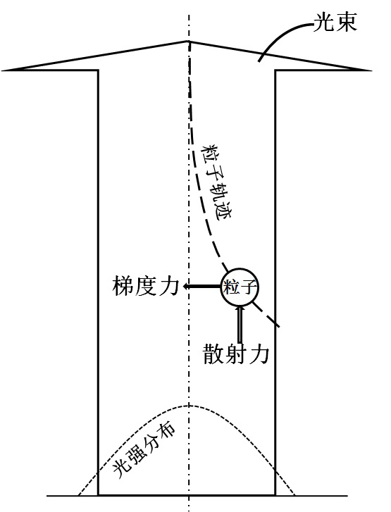
[0038] Embodiment two: see figure 1 and image 3 , the particles ejected from the ejection nozzle 2 move forward into the light field emitted by the strong beam 5, and the intensity of the light field has a certain distribution. In the light field, the particle receives two forces exerted by the light beam on it, one is the scattering force along the direction of the optical axis (usually the light pressure), and the other is the gradient force of the light field perpendicular to the direction of the optical axis. Under the action of the scattering force, the particles accelerate along the direction of the optical axis, and under the action of the gradient force of the light field, the particles will move towards the region with the highest intensity of the light field. Therefore, when the light intensity and its light field gradient are large enough, under the action of these two forces, the particles will eventually overcome the scattering caused by the diffusion process...


PUM


Abstract

The invention relates to a vacuum photoconductive molecular / atomic gas micro-injection device which comprises a gas source and an injection nozzle, wherein the gas source is connected with the injection nozzle, and the injection nozzle is used for injecting a molecular / atomic gas jet flow to a target disk to be sprayed; the device is provided with a guide light source, and strong beams generated by the guide light source or / and the target disk limit the gas jet flow to form an approximately closed tapered or pocket-shaped area in front of the molecular / atomic gas jet flow, so that the molecular / atomic gas jet flow is not spread outside the tapered or pocket-shaped area. The device operates in an approximately vacuum environment, and most of the molecular / atomic gas jet flow moves within the tapered or pocket-shaped area formed by the strong beams and the target disk under the action of strong lights, thus finally realizing directional injection or deposition on the target disk. The device provided by the invention can be applied to the process fields such as micro-injection forming, vacuum thermal evaporation, micro-precision processing, precise micro point / surface coating, coating, microelectronic circuit manufacturing and welding, and the like.

Description

technical field [0001] The invention relates to a vacuum photoconductive molecule / atomic gas micro-spraying device. It can realize the directional spraying or deposition process of molecular / atomic gas jet, thus realizing the precise control of the spraying process. The invention can be used in technical fields such as micro-spray molding, vacuum thermal evaporation, micro-precision machining, precise micro-dot / surface spraying, coating, microelectronic circuit manufacturing and welding. Background technique [0002] The invention originates from the research on the spray forming metallurgy technology and the vacuum thermal evaporation coating process in the microelectronics industry, but the meaning of the invention goes beyond the application of these technologies. [0003] The core technology of spray forming metallurgy technology is jet atomization technology. Jet atomization is a process of physically decomposing a continuous jet into small droplets and particles. The ...

Claims


Application Information

Patent Timeline
Patent Type & Authority Applications(China)
IPC IPC(8): C23C4/00C23C14/22B23K26/00C23C4/12
Inventor 王志亮徐海丽
Owner SHANGHAI UNIV
Why Eureka
Try Eureka