
Biomass conveying installation for feeding into a pressurised container

A pressure vessel, biomass technology, applied in the direction of conveying bulk materials, conveyors, presses, etc., can solve the problems of inability to realize biomass, high production costs, etc., and achieve the effect of avoiding blockage or looseness and large cross-section

Inactive Publication Date: 2011-04-06
卡尔-海因茨·特茨拉夫
View PDF16 Cites 8 Cited by
  • Summary
  • Abstract
  • Description
  • Claims
  • Application Information

AI Technical Summary

Problems solved by technology

However, this method entails high production costs in terms of generating the fluid
[0006] It can likewise be deduced that in a practical application where lignite is fed into a vortex bed driven with a slight overpressure for the production of heat for a thermal power plant, it is not possible to transport biomass to increased pressures above 2 bar. transfer in pressure vessel

Method used


Image

  • Biomass conveying installation for feeding into a pressurised container
  • Biomass conveying installation for feeding into a pressurised container

Examples


Embodiment Construction

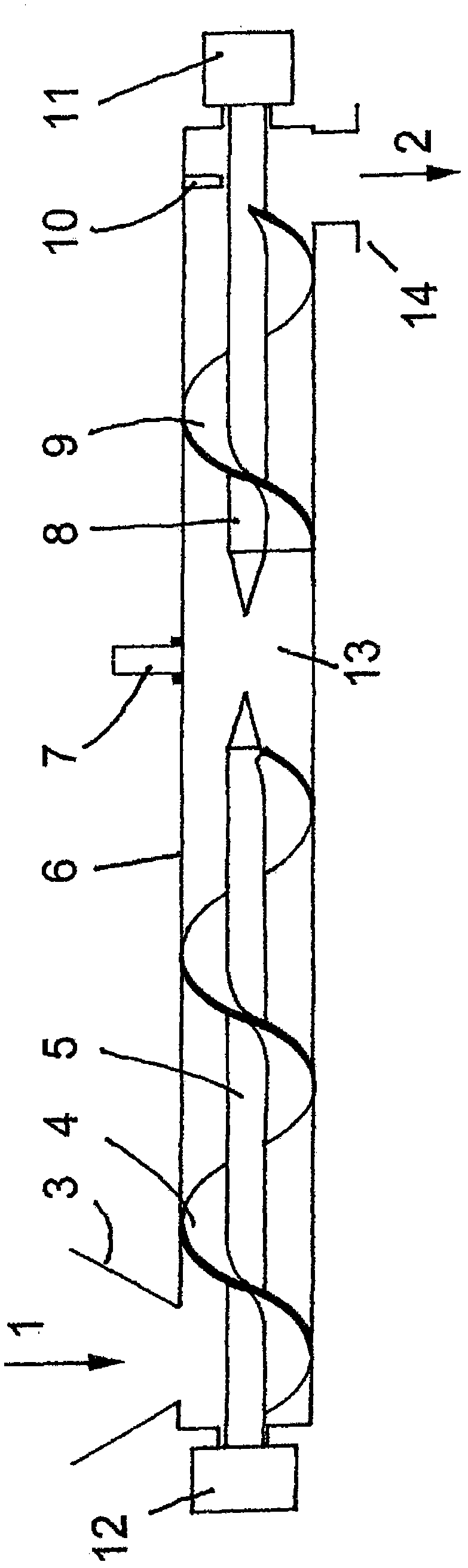
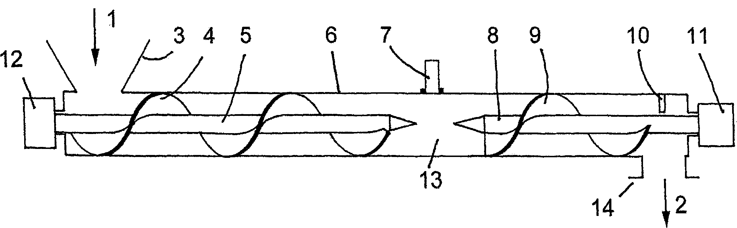
[0023] The biomass 1 is fed at the funnel 3, for example by a receiver with a swivel guide, and leaves the conveying device at the outlet 2 via the flange 14, which is connected to a container or The next level of conveying device is connected. The biomass 1 first flows through the main screw conveyor, which consists of a screw duct 6 , a screw shaft 5 and a screw flight 4 . The biomass 1 is then conveyed through a pipe section 13 without any conveying components. The plunger body made of biomass formed in this pipe section 13 is conveyed further into a secondary screw conveyor, which is formed from a spiral pipe 6 , a screw shaft 8 and a screw flight 9 . At the end of the conveying stroke, the biomass enters an overpressurized space at the outlet 2 . It has proven to be advantageous to arrange a passive or active cutting device 10 at the end of the transport path.

[0024] The rotational speed of the main screw conveyor driven by the motor 12 largely determines the conveyi...


PUM


Abstract

Two independently controllable worms are arranged in a worm conveyor tube (6). The biomass is compressed by high pressure, between the primary worm driven by the motor (12) and the secondary worm driven by the motor (11), as a result of different rotational speeds of the motors (11, 12), in such a way that an almost gas-tight plug (13) is formed. The invention is suitable especially for introducing biomass into a pressurised gasification installation for producing synthesis gas.

Description

technical field [0001] The invention relates to a method and a device for feeding biomass into a vessel under overpressure. An advantageous application of the invention is the introduction of biomass into a booster gasifier for the production of synthesis gas. Background technique [0002] In the gasification unit, in order to produce synthesis gas, the gasification unit needs to be under a pressurized condition of 2 to 100 bar, preferably 12 to 40 bar. Especially suitable for use in industrial production plants in which the synthesis gas can be further processed into other products, and the synthesis gas or its subsequent products can be introduced into the pressurized pipeline network, or the synthesis gas can be made in combustion in the turbine. [0003] In the state of the art, biomass gasification plants with a rated overpressure either use a rotary guide (Zellenradschleusen) or a pressure guide (Druckschleusen), in which the integrated conveyor screw without a press...

Claims


Application Information

Patent Timeline
Patent Type & Authority Applications(China)
IPC IPC(8): B65G53/48C10J3/50C10J3/56B30B11/24
CPCC10J2200/158B65G53/48C10J3/30C10J2300/0916Y02E20/18B30B9/163B30B9/166Y02P20/145
Inventor 卡尔-海因茨·特茨拉夫
Owner 卡尔-海因茨·特茨拉夫
Learn More