Wide rotation speed range output permanent magnet constant speed generator system

A generator and wide speed technology, applied to synchronous motors with stationary armatures and rotating magnets, electrical components, electromechanical devices, etc. Power control and other issues to achieve the effect of simple structure, low cost and high reliability

Active Publication Date: 2012-05-30
HARBIN INST OF TECH
View PDF0 Cites 0 Cited by
  • Summary
  • Abstract
  • Description
  • Claims
  • Application Information

AI Technical Summary

Problems solved by technology

[0004] In order to solve the problems that the maximum energy capture cannot be achieved, the maximum power control cannot be realized, and the generator cannot output electric energy at low speed; even if the maximum power control can be realized, there are still problems such as complex control, high technical difficulty, high cost, and low reliability. A wide speed range output permanent magnet variable speed generator system is proposed

Method used


Image

  • Wide rotation speed range output permanent magnet constant speed generator system
  • Wide rotation speed range output permanent magnet constant speed generator system
  • Wide rotation speed range output permanent magnet constant speed generator system

Examples


specific Embodiment approach 1

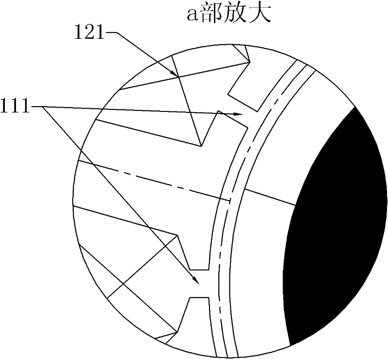
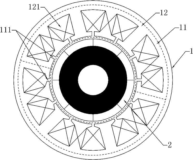
[0008] Specific implementation mode one: combine Figure 1 to Figure 5 Describe this embodiment, the permanent magnet synchronous generator described in this embodiment is composed of a stator 1, a rotor 2 and an air gap, the stator 1 is composed of an armature core 11 and a winding 12, the number of slots and the number of teeth of the armature core 11 Both are 6n, and every other tooth is wound with a coil 121, wherein n is a positive integer, and n≥2; the winding 12 is a concentrated winding composed of 3n coils 121, and every adjacent 3n / j along the circumferential direction Coils 121 form a set of three-phase windings, that is, j sets of three-phase windings are formed for the 3n coils 121, wherein n is an integer multiple of j, and j≠1, each set of three in the j sets of three-phase windings The number of turns of each coil 121 in the phase windings is the same, and the number of turns of the coils 121 between the j sets of three-phase windings is different; the output e...

specific Embodiment approach 2

[0009] Specific embodiment two: the difference between this embodiment and specific embodiment one is that the slot width of the slot where the coil with multiple turns is located is 0.2 to 1.0 times the slot width of the slot where the coil with few turns is located, and the slot width of the slot where the coil with multiple turns is located The notch depth is 1.0-5.0 times of the notch depth of the slot where the coil with few turns is located. Other compositions and connection methods are the same as those in Embodiment 1.

specific Embodiment approach 3

[0010] Embodiment 3: This embodiment differs from Embodiment 1 or Embodiment 2 in that the width of the teeth with coils is different from that of teeth without coils. Other compositions and connection modes are the same as those in Embodiment 1 or 2.


PUM


Abstract

The invention discloses a wide rotation speed range output permanent magnet constant speed generator system. The system relates to the field of motors and solves the problem that the traditional motors cannot capture energy to the maximum. Both slot number and tooth number are 6n and a coil is wound every other tooth, wherein n is a positive integer and is more than or equal to 2. A winding is anintegrated winding consisting of 3n coils; every adjacent 3n / j coils form a set of three-phase windings along the peripheral direction, namely 3n coils form j sets of three-phase windings, wherein n is an integral multiple of j; j is not equal to 1; the turn number of each coil of each set of three-phase winding in the j sets of three-phase windings is the same; and the turn number of the coils among the j sets of three-phase windings is different. The outputs ends of the j sets of three-phase windings are connected with the alternating current input ends of j three-phase rectifiers respectively and the direct current output ends of the j three-phase rectifiers are connected in parallel to form a general output end. The pole number of a rotor is 6n+ / -kn, wherein k is equal to 1 or 2, and n and k cannot be odd numbers at the same time. The generator system can be applied to the variable speed generation field of vehicle generation, wind power generation, small-sized waterpower generation and the like.

Description

technical field [0001] The invention relates to a permanent magnet variable-speed generator system with wide speed range output, belonging to the field of motors. Background technique [0002] The permanent magnet motor has many advantages as a generator. Because the excitation winding and the collector ring and brush that are prone to failure are omitted, the structure is relatively simple, the processing and assembly costs are reduced, and the operation is more reliable. The rare earth permanent magnet generator has significant advantages such as small size, light weight, high efficiency, and flexible shape and size of the motor; at the same time, due to the small permeability of the permanent magnet in the direct axis magnetic circuit, the direct axis armature The reaction reactance is much smaller than that of the electric excitation synchronous generator, so the inherent voltage adjustment rate is smaller than that of the electric excitation synchronous generator. ( I...

Claims


Application Information

Patent Timeline
Patent Type & Authority Patents(China)
IPC IPC(8): H02K21/16H02K11/00H02K1/27
Inventor 寇宝泉白崟儒曹海川
Owner HARBIN INST OF TECH
Why Eureka
Try Eureka