
Infrared bridge type temperature measurement sensor

A temperature measurement sensor and bridge-type technology, applied in the sensor field, can solve the problems of low Seebeck coefficient, limited temperature resolution of infrared temperature measurement sensor, larger output resistance of thermopile, etc., so as to improve work adaptability and sensitivity. , the effect of improving the accuracy

Inactive Publication Date: 2011-03-30
YANTAI RAYTRON TECH
View PDF6 Cites 4 Cited by
  • Summary
  • Abstract
  • Description
  • Claims
  • Application Information

AI Technical Summary

Problems solved by technology

The Seebeck coefficient of commonly used thermocouple materials is usually not high, for example, the temperature sensitivity coefficient of silicon-Al thermocouple is only 0.1% / K, even the thermoelectric coefficient of BiSb (bismuth antimonide) with high temperature sensitivity coefficient is only 0.5 % is about 1 / 4 of the thermistor resistance coefficient (2% / K) of the vanadium oxide film, which limits the temperature resolution of the infrared temperature sensor
Although the response sensitivity of the sensor can be improved by using a thermopile in series with thermocouples, the series connection of thermocouples also causes two problems: first, the output resistance of the thermopile becomes larger, and the noise of the device increases; secondly, the thermopile between the cold end and the hot end Lines will increase the thermal conductivity between the sensitive area of ​​the device and the substrate, which will lead to a decrease in the temperature resolution of the device. Therefore, it is difficult to achieve high-precision temperature measurement using thermopile technology

Method used


Image

  • Infrared bridge type temperature measurement sensor
  • Infrared bridge type temperature measurement sensor
  • Infrared bridge type temperature measurement sensor

Examples


Embodiment Construction

[0023] The principles and features of the present invention are described below in conjunction with the accompanying drawings, and the examples given are only used to explain the present invention, and are not intended to limit the scope of the present invention.

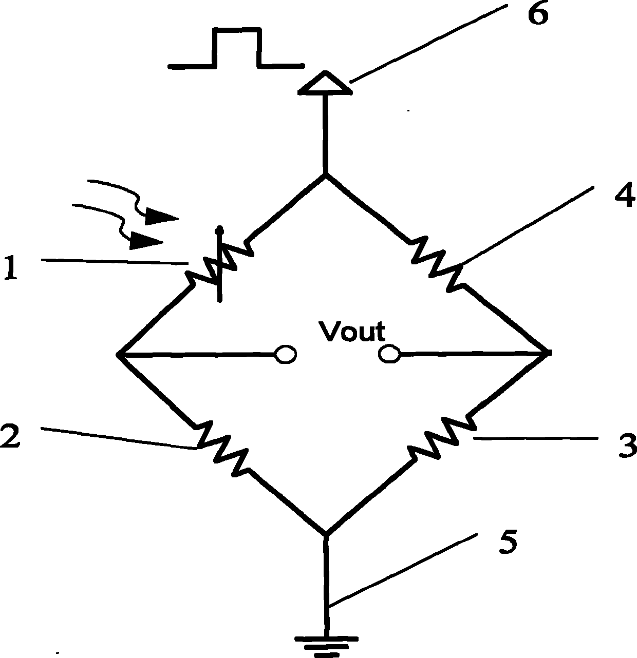
[0024] Such as figure 1 As shown, the sensor embodiment of the present invention includes photoresistor 1, environment reference resistor 2, environment reference resistor 3, Joule heat reference resistor 4, power ground 5 and power supply 6, the photoresistor 1, environment The reference resistor 2, the environment reference resistor 3, and the Joule heat reference resistor 4 are all fabricated on the substrate, and the substrate can be made of silicon or glass, and other materials that can be used as sensor substrates. The present embodiment 1 takes the silicon substrate as an example . In order to reduce the resistance temperature rise caused by Joule heat, the sensor adopts the pulse power supply mode, and the ...


PUM

PropertyMeasurementUnit
Depthaaaaaaaaaa

Abstract

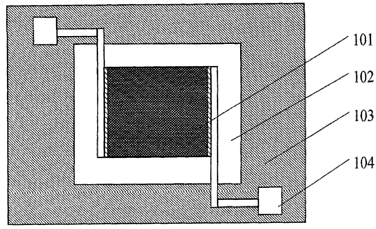
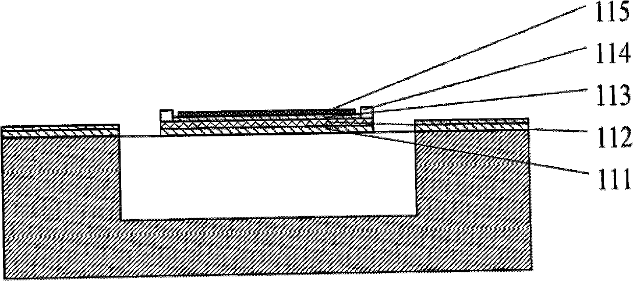
The invention relates to an infrared bridge type temperature measurement sensor, which comprises a substrate and a resistor bridge consisting of four resistors. The sensor is characterized in that: the resistor bridge has an annular structure formed by connecting a photosensitive resistor, two environmental reference resistors and a joule reference resistor end to end; and the position, where the photosensitive resistor and the joule reference resistor are arranged, of the substrate is provided with a groove. The bridge type structure adopted by the sensor is favorable for reducing the influence of environmental temperature and joule heat on the output signals of the sensor and improving the working adaptability of the sensor; the target temperature can be effectively judged according to the magnitude of the bridge output signals; the sensitivity of the sensor is effectively improved by using the photosensitive resistor, the joule reference resistor and the environmental reference resistors; and the substrate below the photosensitive resistor and the joule reference resistor is provided with the groove structure so as to improve the accuracy of temperature measurement.

Description

technical field [0001] The invention relates to a temperature measuring sensor, in particular to an infrared bridge temperature measuring sensor, which belongs to the field of sensors. Background technique [0002] Due to the unique advantages of non-contact, wide dynamic range of temperature measurement and accurate temperature measurement, infrared temperature measurement has a very wide range of applications in food, medical, electric power, industry, construction and other fields. The infrared temperature sensor is the key component of the infrared temperature measuring instrument, and its performance determines the accuracy of the temperature measuring instrument. At present, infrared temperature sensors are mostly produced using the principle of thermopile. US Patent US-5059543 discloses a typical manufacturing method of thermopile infrared sensors, which includes using silicon anisotropic etchant on the silicon substrate Backside etching, etching the silicon in the c...

Claims


Application Information

Patent Timeline
IPC IPC(8): G01J5/24G01J5/22
Inventor 王宏臣
Owner YANTAI RAYTRON TECH
Learn More