High-power light-emitting diode (LED) impulse adjustable stroboflash device

A pulse and pulse parameter technology, applied in the field of light source lighting devices, can solve the problems of low flash pulse precision, slow flash frequency, and inability to use high-precision scientific research.

Inactive Publication Date: 2011-03-30
康亚静
View PDF3 Cites 6 Cited by
  • Summary
  • Abstract
  • Description
  • Claims
  • Application Information

AI Technical Summary

Problems solved by technology

[0003] Most of the existing stroboscopic light-emitting devices on the market are mainly used to measure the rotational speed and surface defects, which determines the flash pulse width (millisecond level) and the slow flash frequency; Electronic tubes, so the life of the flash will not be too long; these flash devices generally do not have a trigger pulse output, so it is difficult to cooperate with other equipment such as photographic devices to take instant photos
In addition, the flash pulse precision of these strobe devices is low, generally on the order of milliseconds, and cannot be used for high-precision scientific research, especially for measuring high-speed moving objects

Method used


Image

  • High-power light-emitting diode (LED) impulse adjustable stroboflash device
  • High-power light-emitting diode (LED) impulse adjustable stroboflash device

Examples


Embodiment Construction

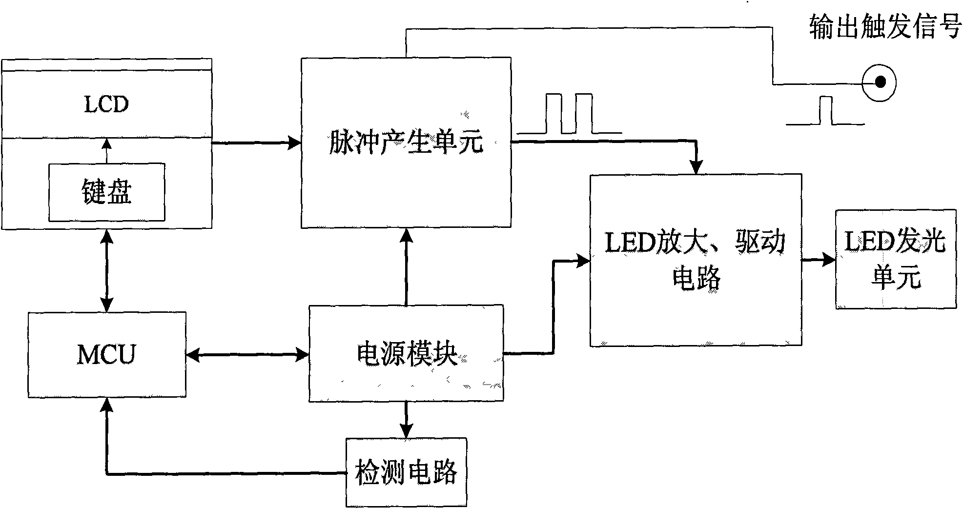
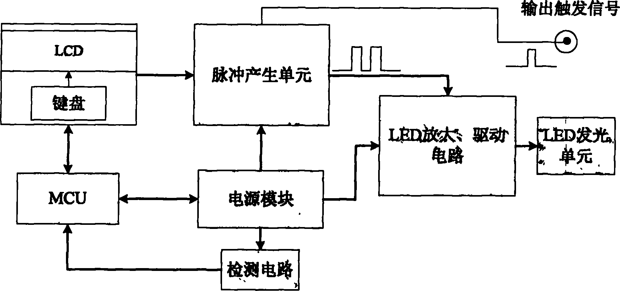
[0015] Such as figure 1 As shown, it includes LCD display and keyboard input unit (including single-chip microcomputer) for inputting pulse parameters, pulse unit for generating pulses, LED drive circuit for driving and amplifying current, and power supply module for supplying power to the entire system , LED flash unit for flash.

[0016] The single-chip microcomputer program in the LCD display and keyboard input unit repeatedly scans the keyboard input, and when receiving the pulse parameters of the keyboard input, the LCD displays the input pulse width, pulse interval, pulse number, and time delay of the external trigger pulse. Parameters, when the "OK" key of the keyboard is received, a series of rectangular pulses are generated to send the pulse parameters to the pulse parameter storage circuit of the pulse generating unit. The single-chip microcomputer scans the status of the power module from time to time. Once the power supply is found to be in an abnormal state, it w...


PUM


Abstract

The invention provides a high-power light-emitting diode (LED) impulse adjustable stroboflash device, comprising a display and input unit, an impulse generation unit, a drive and amplification unit and an LED luminescent unit. A liquid crystal display (LCD) and keyboard input unit inputs impulse width, impulse interval and trigger delay, field programmable gate array (FPGA) is used for designing a synchronous impulse generation circuit, and a high-power LED is used as a lighting source, wherein the LCD and keyboard input unit sets impulse width, impulse interval, trigger time and duty cycle, sets information and sends the information to the impulse generation circuit; the impulse generation circuit generates corresponding impulse according to the set impulse information to the LED drive and amplification circuit so as to perform LED flash. The device controls the LED to flash by adopting synchronous trigger technology, and triggers a high-speed camera, a streak camera and other camera devices to start a shutter for capturing instant information. The LED lamp is in a closed sate when no trigger impulse is generated so as to realize energy conservation and environmental protection.

Description

technical field [0001] The invention relates to a light source lighting device in a measurement and monitoring system in the field of ultrafast phenomena, especially a pulse-adjustable stroboscopic lighting device. Background technique [0002] In the research fields of fluid mechanics, detonation physics, and engineering practice, it is often necessary to measure the speed, take pictures, and control parameters of fast-moving objects such as high-speed flying projectiles, explosive properties, fragments when objects explode, and high-speed rotating shafts. , due to the extremely high speed of the object, a high-speed camera must be used to record and observe it. However, most of these objects cannot emit light by themselves. When measuring, a supporting lighting device and a precise synchronous control system are required to make the image recording equipment photosensitive and imaged. It is against this background that the design of high-power LED pulse can strobe device....

Claims


Application Information

Patent Timeline
Patent Type & Authority Applications(China)
IPC IPC(8): F21S10/06F21V23/00H05B37/02H05B37/03G05B19/02F21Y101/02
CPCY02B20/40
Inventor 康亚静
Owner 康亚静
Why Eureka
Try Eureka