
Microfluid electrostatic spinning device

A microfluidic device and electrospinning technology, applied in textiles and papermaking, filament/thread forming, fiber processing, etc., to achieve the effects of short process flow, convenient operation and simple structure

Inactive Publication Date: 2011-03-30
JIANGNAN UNIV
View PDF3 Cites 27 Cited by
  • Summary
  • Abstract
  • Description
  • Claims
  • Application Information

AI Technical Summary

Problems solved by technology

However, the fiber structure prepared by these methods is unpredictable, so the preparation of multifunctional nanofibers with controllable structure through the improvement of devices is a necessary step in the preparation of functionalized nanofibers

Method used


Image

  • Microfluid electrostatic spinning device
  • Microfluid electrostatic spinning device
  • Microfluid electrostatic spinning device

Examples


Embodiment Construction

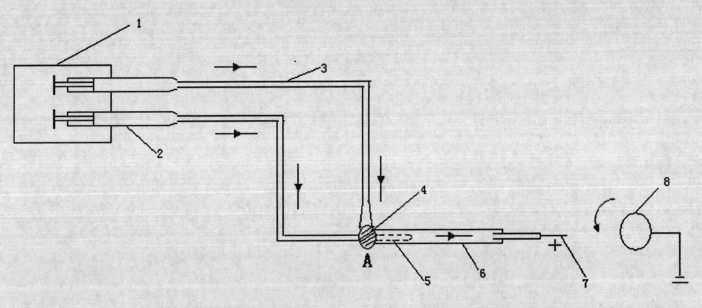
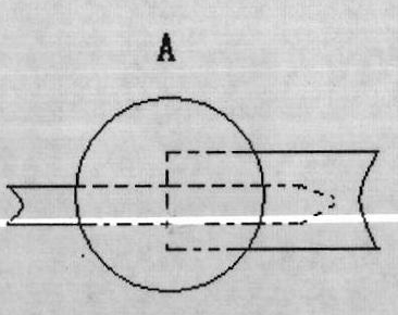
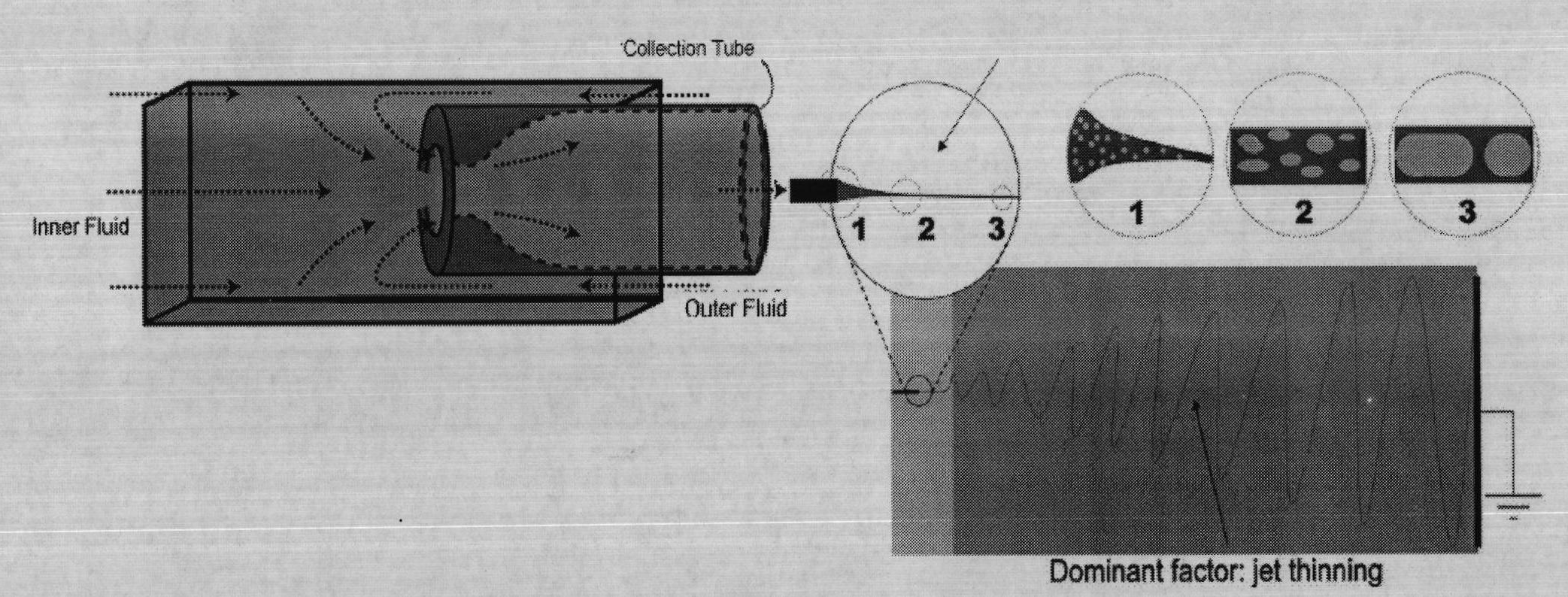
[0013] A microfluidic electrospinning device for preparing a microfluidic-assisted two-phase solution with a predictable structure and a finely regulated composition ratio, which is adopted in the present invention, mainly includes a dual-channel syringe pump 1, a microfluidic device (4, 5, 6 , 7), four parts of drum collection device 8 and high voltage power supply. Among them, the high-voltage power supply adopts DW-P503-4AC CD high-voltage DC power supply; the flow rate of the spinning solution in the inner and outer tubes is controlled by JZB-1800D dual-channel injection pump; the drum is driven by QJ1510S DC stable power supply. The spinning process is as follows: turn on the switch of the dual-channel syringe pump to adjust the flow rate ratio of the inner and outer capillaries corresponding to the syringe → turn on the high-voltage power supply, adjust the voltage, start spinning → turn on the DC stable power supply, and the drum rotates → adjust the flow rate ratio of t...


PUM


Abstract

The invention belongs to the field of spinning field and discloses a microfluid electrostatic spinning device which comprises a dual-channel injection pump, a microfluid device, a high voltage power supply and a roller receiving device, wherein the microfluid device is additionally arranged to the traditional electrostatic spinning device; and the injection pump is the dual-channel injection pump which is capable of individually controlling the boosting speed of a dual-channel injector. Multi-component composite nanofibre with a predicted structure can be woven by the microfluid electrostatic spinning device, and is unique in structure and function. The microfluid electrostatic spinning device ensures that accurate control for proportion of all components of the composite nanofibre, which is realized by the traditional electrostatic spinning technique, can be realized. The microfluid electrostatic spinning device has simple structure, and is convenient in operation and short in technique procedure.

Description

technical field [0001] The invention belongs to the textile field, and relates to a microfluid electrostatic spinning device. technical background [0002] The traditional electrospinning equipment that is widely used at present is composed of three parts: a syringe pump, a high-voltage power supply, and a receiving plate. Its working principle is: the polymer solution or melt is charged with tens of millions to tens of thousands of volts of high-voltage static electricity, and the charged droplets overcome the surface tension under the action of the electric field force to form a jet stream. The charged polymer jet is stretched and thinned under the action of electric field force, viscous resistance, surface tension, etc. At the same time, the charged jet bends, rotates and whips due to the existence of surface charges in the electric field. The thin stream evaporates or solidifies the solvent during the spraying process, and finally falls on the receiving device, forming ...

Claims


Application Information

Patent Timeline
Patent Type & Authority Applications(China)
IPC IPC(8): D01D5/00D01D13/00
Inventor 王清清魏取福李学佳董宪君姚春梅
Owner JIANGNAN UNIV
Learn More