Assembled hot air stove

A hot blast stove, assembled technology, applied in the directions of air heaters, fluid heaters, lighting and heating equipment, etc., can solve the problems of scrapped furnace body, insufficient utilization of combustion heat, waste of resources, etc., to save resources and solve Energy crisis and environmental pollution, the effect of sufficient combustion

Inactive Publication Date: 2011-03-16
朴学哲
View PDF3 Cites 2 Cited by
  • Summary
  • Abstract
  • Description
  • Claims
  • Application Information

AI Technical Summary

Problems solved by technology

[0002] At present, the structure of conventional hot blast stoves generally adopts the structural mode of fixing the combustion part and the heat exchange part as a whole. Once the wearing parts are damaged, it is difficult to replace them, which often leads to the scrapping of the entire furnace body.
This will cause a lot of waste of resources
Moreover, the function of the combustion chamber of the existing hot blast stove is generally only to provide a heat source for the heat exchange part through the furnace, a part of the heat energy is consumed by the thick furnace wall, and the heat energy generated by the combustion is not fully utilized.

Method used


Image

  • Assembled hot air stove
  • Assembled hot air stove
  • Assembled hot air stove

Examples


Embodiment 1

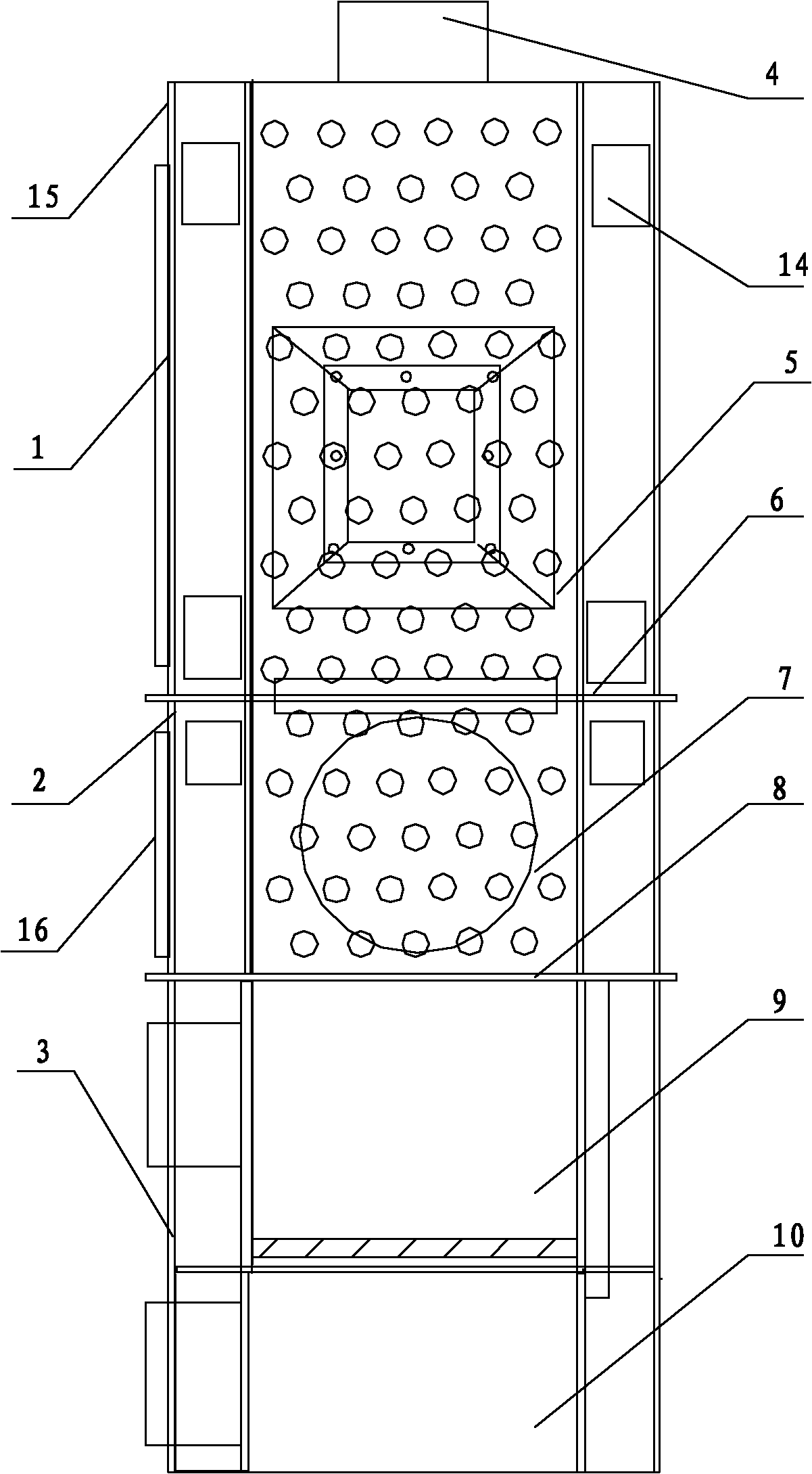
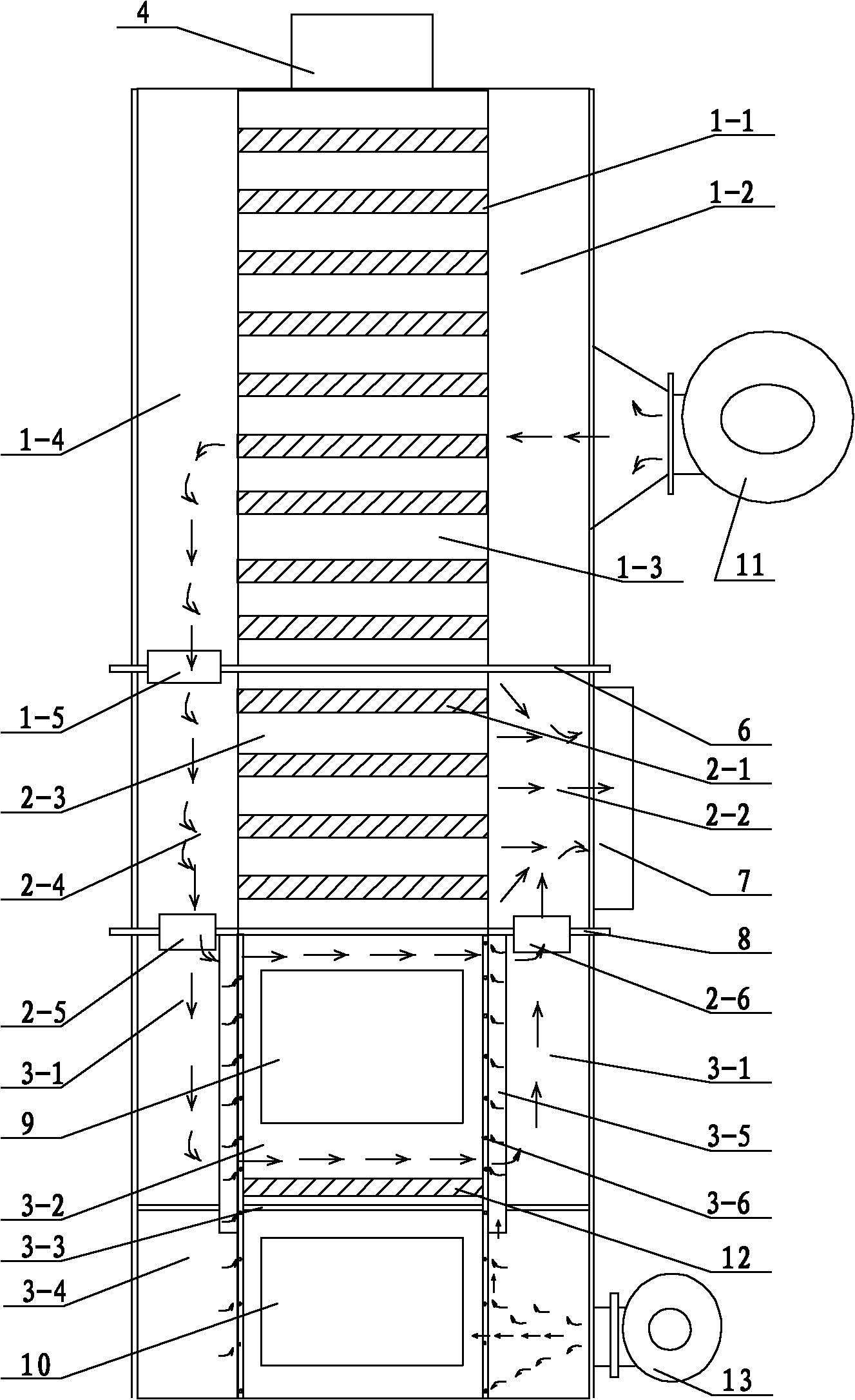
[0026] See figure 1 , figure 2 The fuel of the present invention can use industrial waste, white waste, dry food waste, discarded crops, leftover wood, various coals, etc., and can achieve full combustion, achieving smokeless and dustless effects. It can be widely used in shell-shaped boilers, environmental protection boilers, heaters and drying furnaces, etc., and can also be used as rural household stoves, outdoor heating or field heating.

[0027] The number of air holes in the furnace body 3 of the heat exchange part and the wall of the secondary heating furnace body 2 that lead into the furnace is related to the size of the furnace. The larger the furnace diameter, the more the number of air holes, and vice versa.

[0028] The primary heating furnace body 1 and the secondary heating furnace body 2 of the heat exchange part are sequentially located above the combustion part furnace body 3, the bottom of which is in communication with the combustion chamber of the combustion fur...

Embodiment 2

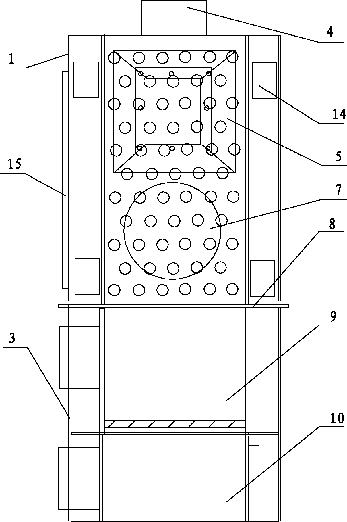
[0030] See image 3 , Figure 4 , The assembled hot blast stove is composed of a combustion part and a primary heating furnace body 1 of the heat exchange part, and the furnace of the combustion part is used to achieve secondary heating. Others are the same as in Embodiment 1.


PUM


Abstract

The invention discloses an assembled hot air stove, and aims to solve the technical problem that: the overall stove is scraped because the conventional hot air stove structure adopts a structural mode that a combustion part and a heat exchanging part are integrally fixed, and once quick-wear parts are damaged, the damaged parts are difficult to replace. The assembled hot air stove comprises the combustion part and the heat exchanging part, wherein the heat exchanging part positioned above the combustion part consists of a primary heating stove body and a secondary heating stove body; groups of primary heating pipes and secondary heating pipes are arranged in the hearth chambers of the two heating stove bodies respectively; the stove body of the combustion part which has a steel board structure is connected with the primary heat exchanging stove body and the secondary heat exchanging body of the heat exchanging part by flanges respectively; air is fed into the two heating stove bodies and the combustion hearth of the heat exchanging part by air blowing boxes and hot air-connecting air passages on the side walls of the stove bodies; the hot air subjected to heat exchange flows into an air-discharging storage box; and a heat source is fed out by a hot air outlet. The assembled hot air stove has the characteristics that the oxidation supply in the hearth is even and abundant, a contact area of the combustion stove and the heat exchanging device is large, the heat source use ratio of the combustion stove is improved, and it is convenient for changing quick-wear parts by using an assembly structure for the stove body.

Description

Technical field: [0001] The invention relates to a hot blast stove, in particular to an assembled hot blast stove. The hot blast stove is suitable for shell-shaped boilers, environmental protection boilers, warm air stoves and drying stoves, and can also be used as rural household stoves, outdoor heating or field heating. Background technique: [0002] At present, the structure of conventional hot blast stoves generally adopts the structural mode of fixing the combustion part and the heat exchange part as a whole. Once the wearing parts are damaged, it is difficult to replace them, often resulting in the scrapping of the entire furnace body. This will cause a lot of waste of resources. And the effect of the combustion chamber of existing hot blast stove generally only is to provide heat source for heat exchange part through furnace hearth, and a part of heat energy is consumed by thick furnace wall, and the heat energy that combustion produces is not fully utilized. Inven...

Claims


Application Information

Patent Timeline
IPC IPC(8): F24H3/08
Inventor 朴学哲
Owner 朴学哲
Why Eureka
Try Eureka