
End mill with unequal helical angles

An end mill and helix angle technology, applied in the field of metal cutting, can solve the problems of small chip space at the bottom of the groove, poor strength and rigidity of the cutting edge, unfavorable chip curling and discharge, etc., to improve cutting efficiency and durability. , Improve the surface quality, strength and good chip removal effect

Active Publication Date: 2011-03-09
ZHUZHOU CEMENTED CARBIDE CUTTING TOOLS CO LTD
View PDF5 Cites 13 Cited by
  • Summary
  • Abstract
  • Description
  • Claims
  • Application Information

AI Technical Summary

Problems solved by technology

However, in such unequal helix angle end mills, the end mill is tangent to the core thickness circle in a concave curve from the front to the face, and then extends linearly from the tangent point to the end mill flank , therefore, the chip discharge groove has a small space for chips at the bottom of the groove, which is not conducive to chip curling and discharge
In addition, the straight portion of the chip discharge flute intersects the groove bottom surface of the flank at an obtuse angle, and the land width of the cutting edge on the rear side in the rotation direction of the end mill is narrowed, so the strength and rigidity of the cutting edge of the end mill deteriorate.

Method used


Image

  • End mill with unequal helical angles
  • End mill with unequal helical angles
  • End mill with unequal helical angles

Examples


Embodiment Construction

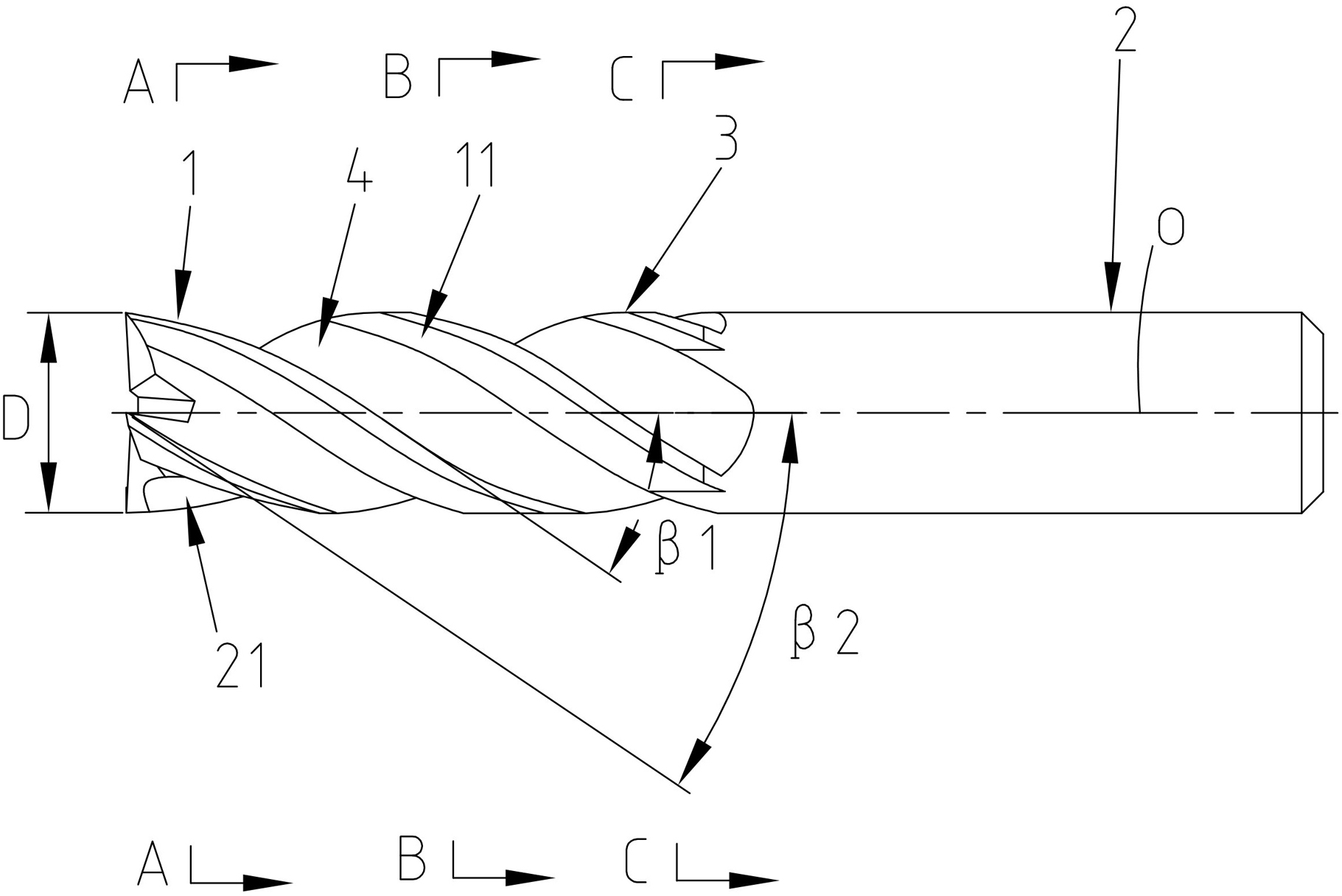
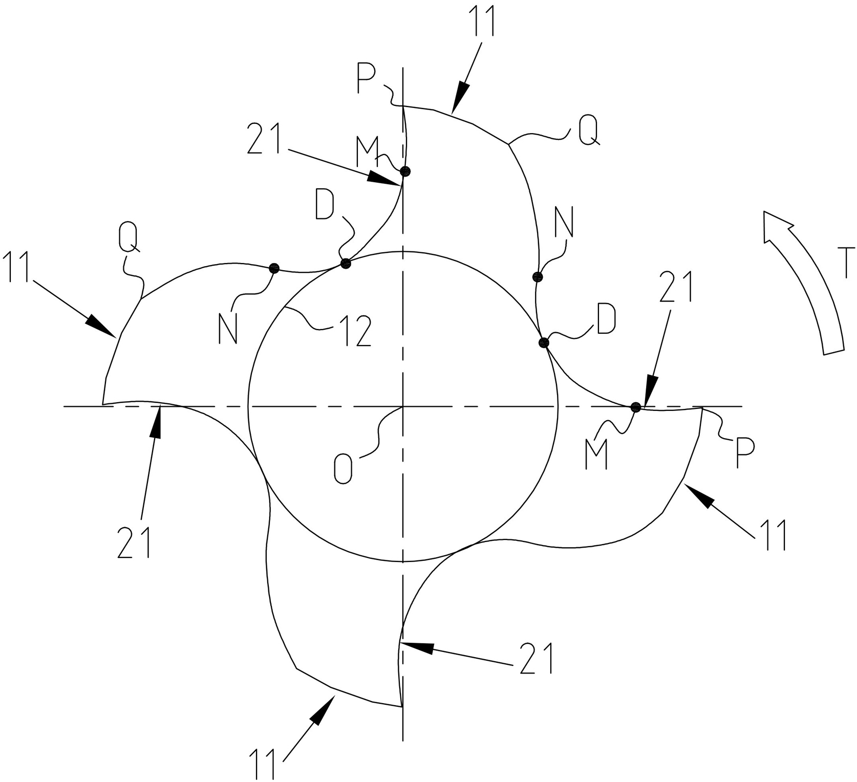
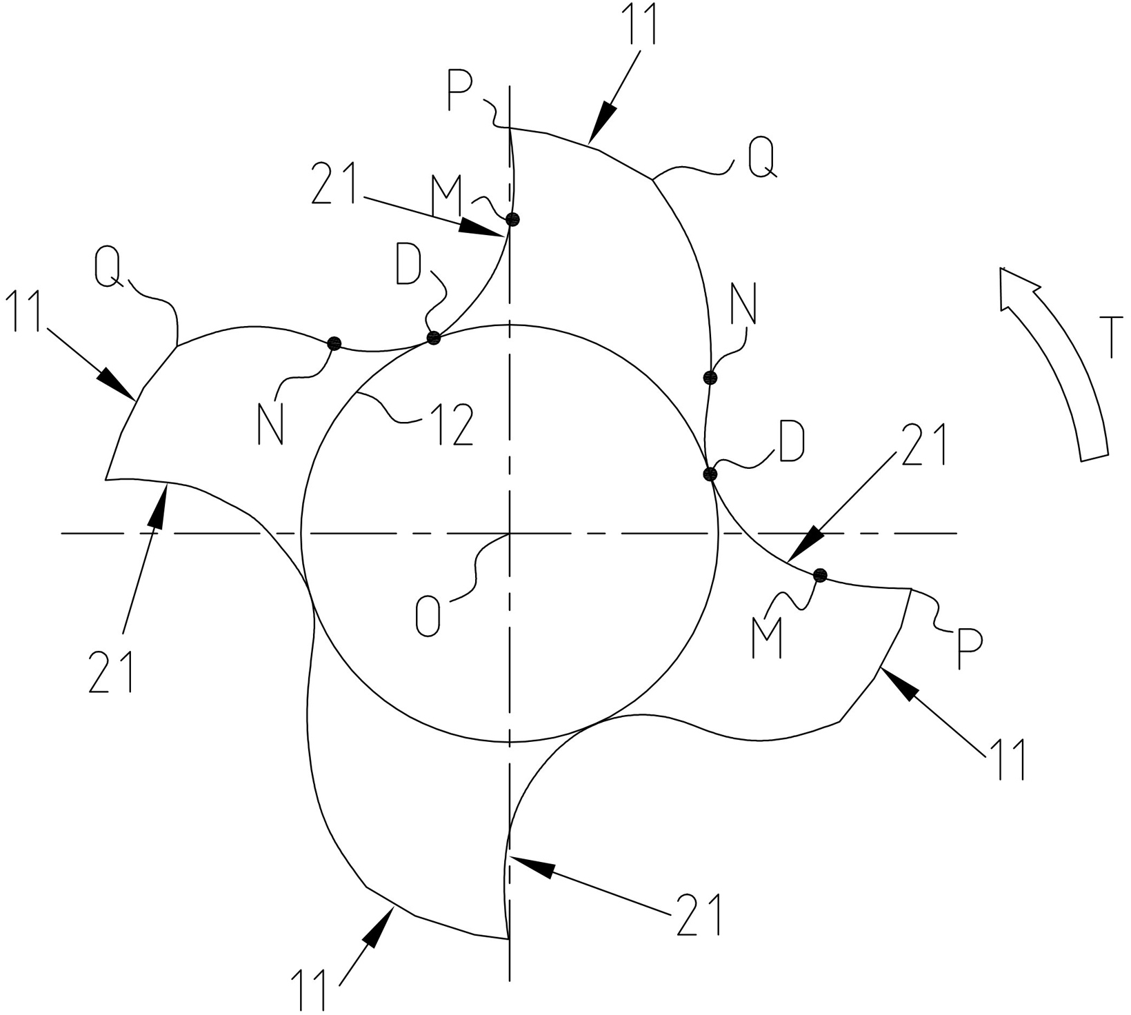
[0019] Figure 1 to Figure 4 An embodiment of the unequal helix angle end mill of the present invention is shown. The end mill is made of a cemented carbide material in a cylindrical shape. One end of the end mill is a cylindrical shank 2 and the other end is a cutting portion 1. The shank 2 is used to connect the machine tool spindle, and the machine tool spindle drives the end mill to rotate and cut the workpiece in the T direction. The entire cutting portion 1 is provided with a plurality of chip flutes 4 spirally extending from the bottom end to the shank 2. In this embodiment, there are four chip flutes 4, and the four chip flutes 4 are arranged at unequal intervals. The surface of each chip flute 4 facing the cutting rotation direction is the rake face 21. The rake face 21 intersects with the outer peripheral surface of the cutting portion 1 to form a peripheral edge 3, and the helix angle of at least one peripheral edge 3 is different from that of other peripheral edges ...


PUM


Abstract

The invention discloses an end mill with unequal helical angles, which comprises a cutting part and a handle part, wherein the whole cutting part is provided with a plurality of chip discharging grooves which helically extend from the bottom end to the handle part; the surface of each chip discharging groove facing the cutting rotation direction is a front cutting surface; each front cutting surface is crossed with the peripheral surface of the cutting part to form a peripheral blade; the helical angle of at least one peripheral blade is different from the helical angles of other peripheral blades; the surface connected with each peripheral blade in the peripheral surface of the cutting part is a back cutting surface positioned on a plane which is perpendicular to the rotary axis of the end mill; the outline of each chip discharging groove is formed by smoothly connecting a curve PM, a curve MN and a curve NQ; each chip discharging groove extends from a projection point P of each peripheral blade to a projection point M of each front cutting surface in the shape of a concave curve, extends from the point M to a point N in the shape of a concave curve, and extends from the point N in the shape of a convex curve and is crossed with the back cutting surface of each peripheral blade at a point Q; and the curve MN is tangential with the thick-core circle of the end mill at a point D. The end mill with unequal helical angles has the advantages of simple structure and strong vibration resistance and can improve the chip discharging property.

Description

Technical field [0001] The invention relates to the field of metal cutting processing, in particular to a unequal helix angle end mill. Background technique [0002] Milling is a discontinuous machining process. During the milling process, the cutting motion between the end mill and the material to be processed makes it subject to impact loads, causing the end mill to vibrate. When the end mill's vibration frequency is close to the workpiece Natural frequency will cause resonance, which will seriously affect the processing quality and tool life. In order to reduce or eliminate the vibration of the end mill in the milling process, improve the processing quality and tool life, many improvements have been made to the anti-vibration end mill. For example, the Chinese patent document with the publication number CN101530930 discloses a unequal helix angle vertical Milling cutter, the end mill is formed with a plurality of peripheral edges twisted in a helical shape, and the helix angl...

Claims


Application Information

Patent Timeline
IPC IPC(8): B23C5/10
Inventor 许晋方曙璋王社权李屏
Owner ZHUZHOU CEMENTED CARBIDE CUTTING TOOLS CO LTD
Learn More