Glass melting furnace

A glass melting furnace and melting furnace technology, applied in glass furnace equipment, glass production, glass manufacturing equipment and other directions, can solve problems such as expensive materials

Inactive Publication Date: 2011-02-23
AGC GLASS EUROPE SA
View PDF2 Cites 0 Cited by
  • Summary
  • Abstract
  • Description
  • Claims
  • Application Information

AI Technical Summary

Problems solved by technology

In the case of oxy-fuel combustion furnaces, it is more precisely necessary to resort to materials such as alumina, AZS or spinel, which, on the other hand, are however more expensive and also cause problems due to their significantly heavier weight

Method used


Image

  • Glass melting furnace
  • Glass melting furnace
  • Glass melting furnace

Examples


Embodiment Construction

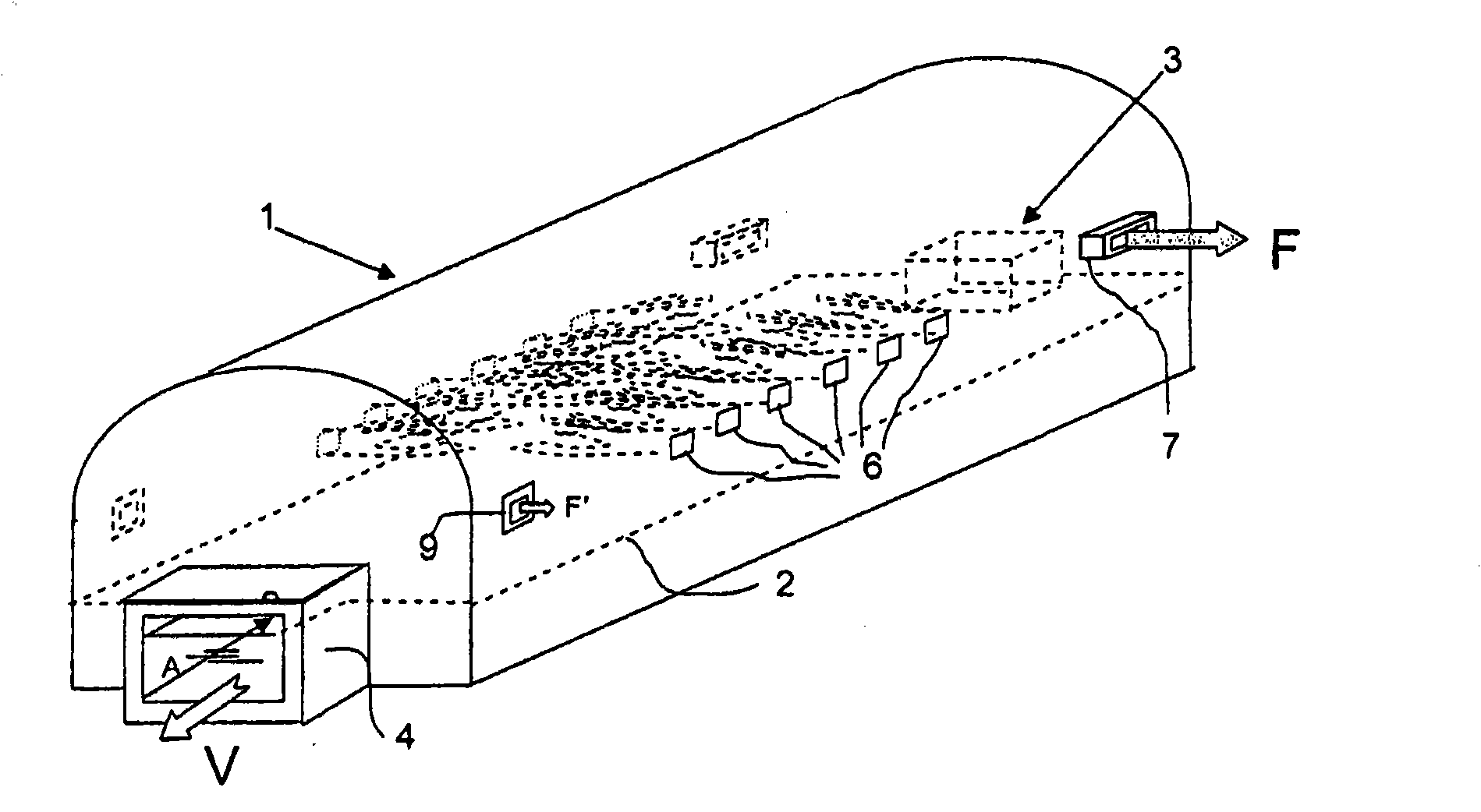
[0088] figure 1 The furnaces shown in are of the type used for bulk glass production, such as those that use suspended glass technology for feeding flat glass. This type of furnace can continuously produce up to 1000 tons / day of glass. To achieve these properties, the furnace must have power up to 60MV.

[0089] The furnace 1 comprises a pool arranged in a closed chamber. The assembly is constructed of a refractory material that is resistant to high temperatures, corrosion by exhaust gases, and corrosion by molten material. The height of the molten bath in the pool is indicated by the dashed line 2 .

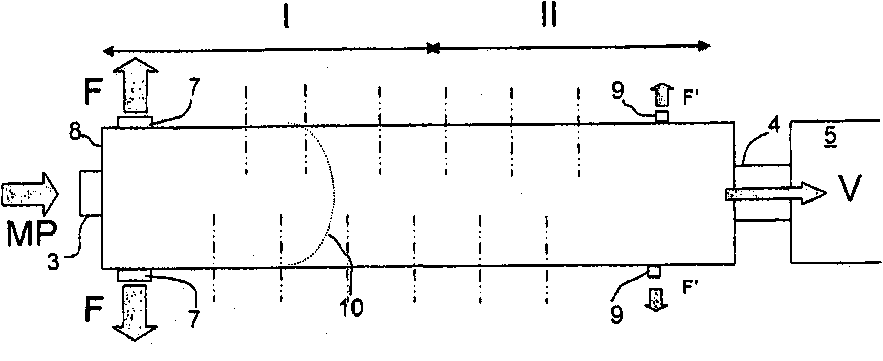
[0090] The furnace is fed raw material at one end of it. The opening through which the raw material is charged into the furnace is shown at 3 . In practice, in order to facilitate distribution over the surface of the molten bath, multiple charging points are usually provided. The output of the molten glass, indicated by the arrow V, takes place at the opposite end through ...


PUM


Abstract

The invention relates to a glass melting furnace including a channel-shaped melting end. According to the invention, the raw materials are introduced at an upstream end and the molten glass is recovered at the downstream end, said furnace being heated by burners. At least 65% of the combustion energy is produced by oxycombustion and the burners are distributed on the walls along the length of the furnace. The majority of the flue gases are released close to the upstream end near the raw material inlets, the remainder being released close to the downstream part such as to maintain a dynamic seal in relation to the surrounding atmosphere.

Description

technical field [0001] The present invention relates to a glass melting furnace in which the melting energy is substantially generated by a burner which is fed with fuel and fed with oxygen or an oxygen-enriched gas. These furnaces are generally defined as "oxy-combustion" furnaces. Background technique [0002] The incidental use of oxy-fuel burners in glass melting furnaces is well known. In the case of furnace operation, usually with air, one or a limited number of oxy-fuel burners are added. The purpose of introducing these additional burners is usually to increase the throughput of existing furnaces, possibly when the performance of existing furnaces is observed to decline due to their age. This happens, for example, when it is found that the heat exchangers associated with such furnaces have become degraded and can no longer adequately heat the air for combustion. The throughput of a given furnace can also be simply increased by introducing a supplementary energy so...

Claims


Application Information

Patent Timeline
Patent Type & Authority Applications(China)
IPC IPC(8): C03B5/235C03B5/04
CPCC03B5/2353C03B5/04Y02P40/50
Inventor O·杜尚J·贝昂
Owner AGC GLASS EUROPE SA
Why Eureka
Try Eureka