
Method for dynamically compensating blind pixel

A blind element compensation and dynamic technology, which is applied in image data processing, optical device exploration, instruments, etc., can solve the problems of strong dependence on front and back frames, and achieve the effect of easy hardware implementation, good versatility, and simple algorithm

Inactive Publication Date: 2011-02-23
UNIV OF ELECTRONICS SCI & TECH OF CHINA
View PDF1 Cites 25 Cited by
  • Summary
  • Abstract
  • Description
  • Claims
  • Application Information

AI Technical Summary

Problems solved by technology

Its advantage is that it can keep the edge of the image very well, and its disadvantage is that it has a strong dependence on the previous and subsequent frames; second, spatial compensation, which compensates it with the help of pixel information around the blind pixel

Method used


Image

  • Method for dynamically compensating blind pixel
  • Method for dynamically compensating blind pixel
  • Method for dynamically compensating blind pixel

Examples


Embodiment Construction

[0020] The present invention will be further described below in conjunction with accompanying drawing:

[0021] Detailed technical scheme of the present invention is:

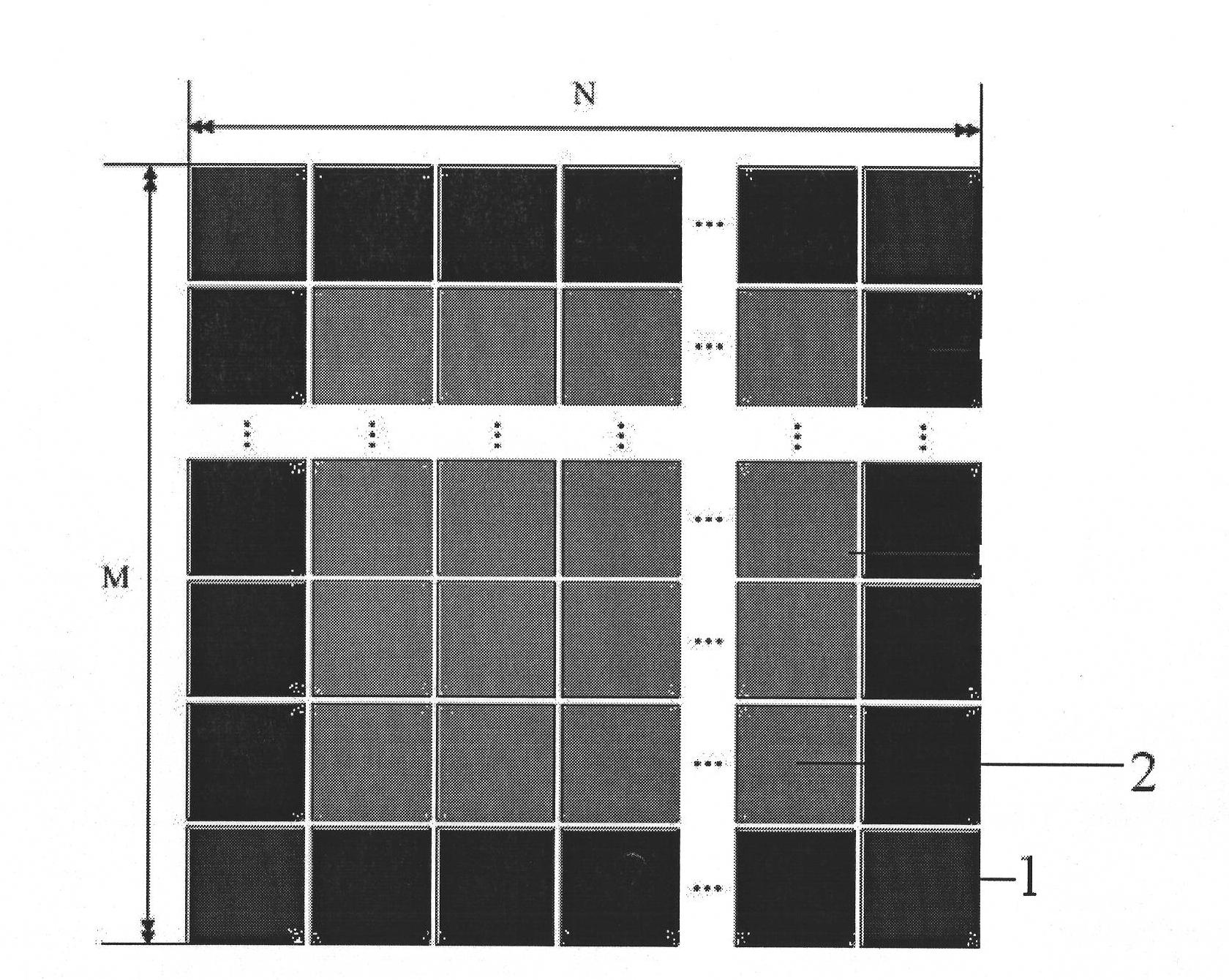
[0022] For an M×N infrared focal plane array, let S(i, j) be a window matrix with a center at (i, j) and a size of 3×3, where i∈(1,M), j∈(1,N ), the pixel grayscale of each pixel in the window is denoted as S k (i, j), k=1, 2K9. S k (i, j) from S 1 (i, j) start to S 9 (i, j) are arranged from small to large, and the grayscale of the median pixel is S 5 (i, j), such as figure 2 .

[0023] The process of median filter blind element compensation algorithm is as follows:

[0024] (1). Move the 3×3 window matrix S(i, j) along the row direction of the image data, that is, the center point (i, j) traverses all points (2, j) from point (2, 2), j =2,3...N-2;

[0025] (2). Each time a point is moved, the pixel gray values ​​of all pixels in S(i, j) are arranged from small to large, such as figure 2 , take th...


PUM


Abstract

The invention discloses a method for dynamically compensating a blind pixel. The method comprises the following steps of: arranging pixel gray values of a 3*3 window matrix dot picture element from small to large according to the remarkable abnormity of the blind pixel in a local window; if the absolute value of the difference value between a medium value and other picture element gray value is greater than a preset threshold value, determining the picture element as the blind pixel; detecting all picture elements of an M*N array by using a medium gray value instead of a blind pixel gray value; and compensating all blind pixels. Therefore, a high-quality image is obtained in a display device.

Description

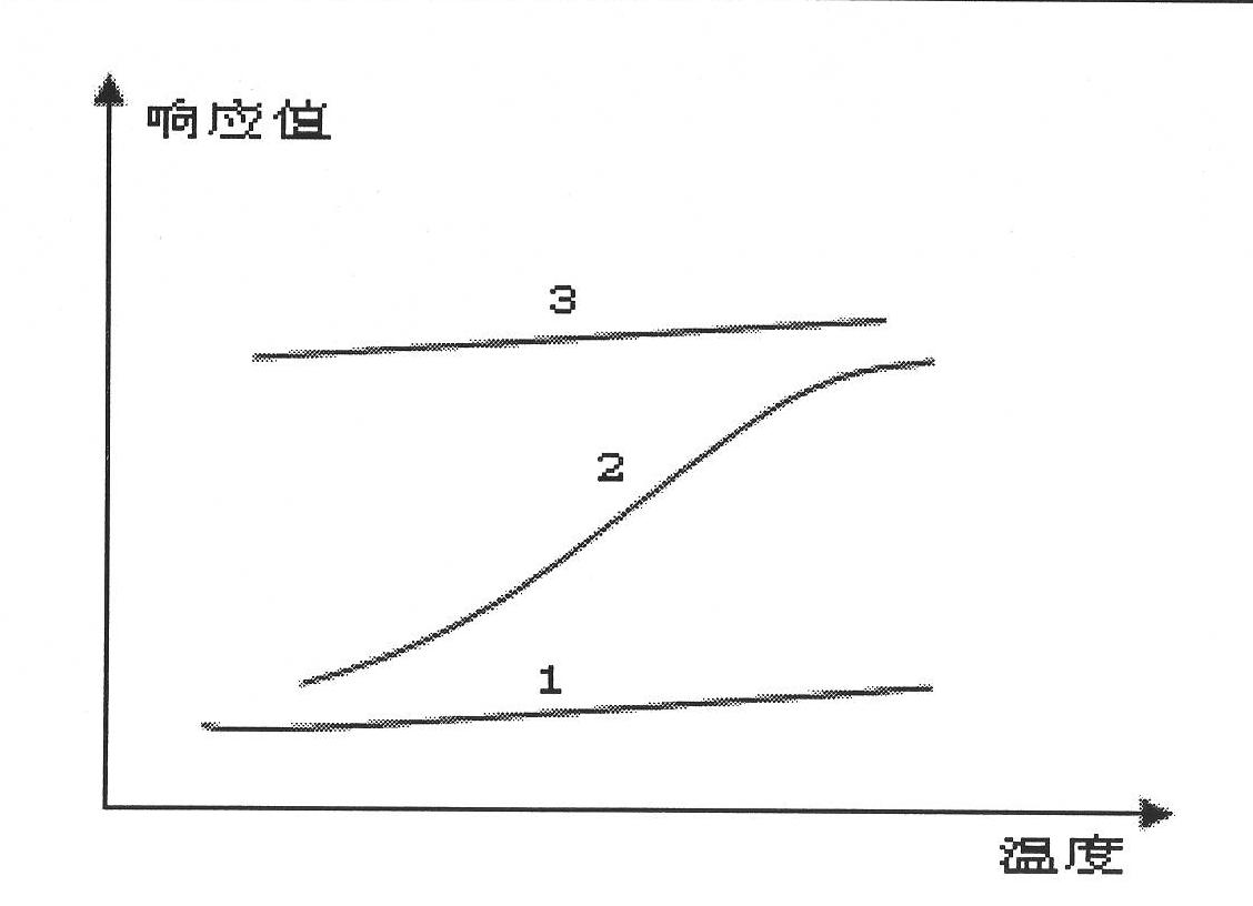
technical field [0001] The invention relates to the technical field of uncooled infrared detection, in particular to an optimized dynamic blind element compensation method in infrared image processing. Background technique [0002] Infrared Focal Plane Array (IRFPA), as the latest generation of detectors, has been widely used in various military and civilian fields. Due to the influence of manufacturing process, materials and other factors, the IRFPA device inevitably has the problem of blind elements, which affects the signal-to-noise ratio of the image output by the infrared imaging system. Blind cells, or invalid cells, refer to the cells whose response is too high or too low in the IRFPA device. The number and distribution of blind pixels seriously affect the output image quality of infrared imaging systems. Blind pixels appear as bright or dark spots in the image. Detection and compensation of blind pixels in the imaging stage can help improve image quality. [0003] ...

Claims


Application Information

Patent Timeline
Patent Type & Authority Applications(China)
IPC IPC(8): G06T5/00G01V8/10
Inventor 蒋亚东刘子骥辛勇明王然郑兴
Owner UNIV OF ELECTRONICS SCI & TECH OF CHINA
Learn More