
Jet cooling device for heat treatment furnace

A technology of cooling device and heat treatment furnace, which is applied in the direction of heat treatment equipment, quenching device, quenching agent, etc., can solve the problem that the cooling speed cannot be realized, and achieve a good cooling effect

Active Publication Date: 2011-02-23
SUZHOU ZHONGMENZI TECH
View PDF4 Cites 9 Cited by
  • Summary
  • Abstract
  • Description
  • Claims
  • Application Information

AI Technical Summary

Problems solved by technology

The spray cooling device implemented according to this patent cannot realize the higher cooling speed requirement of the front section of the workpiece

Method used


Image

  • Jet cooling device for heat treatment furnace
  • Jet cooling device for heat treatment furnace
  • Jet cooling device for heat treatment furnace

Examples


Embodiment Construction

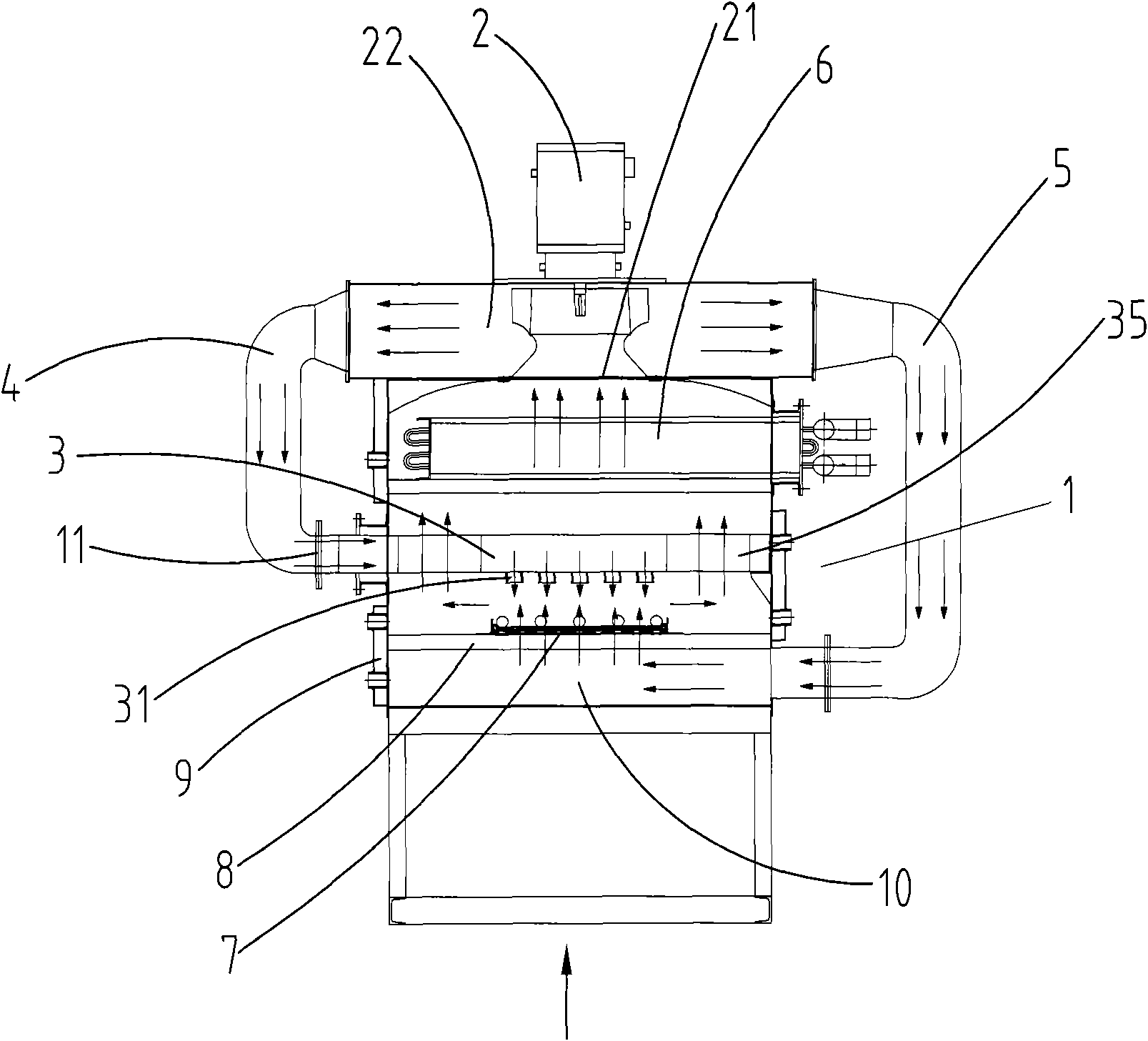
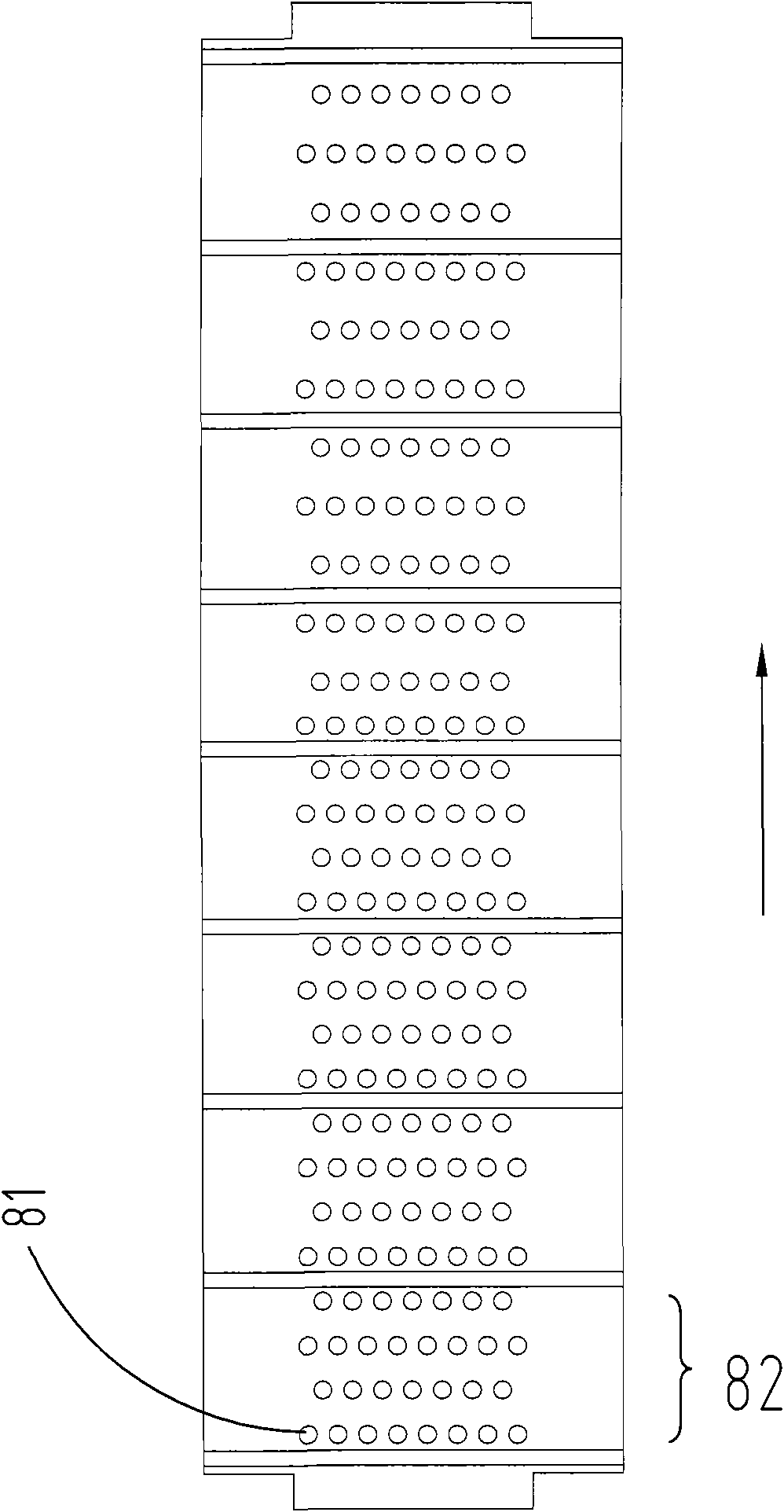
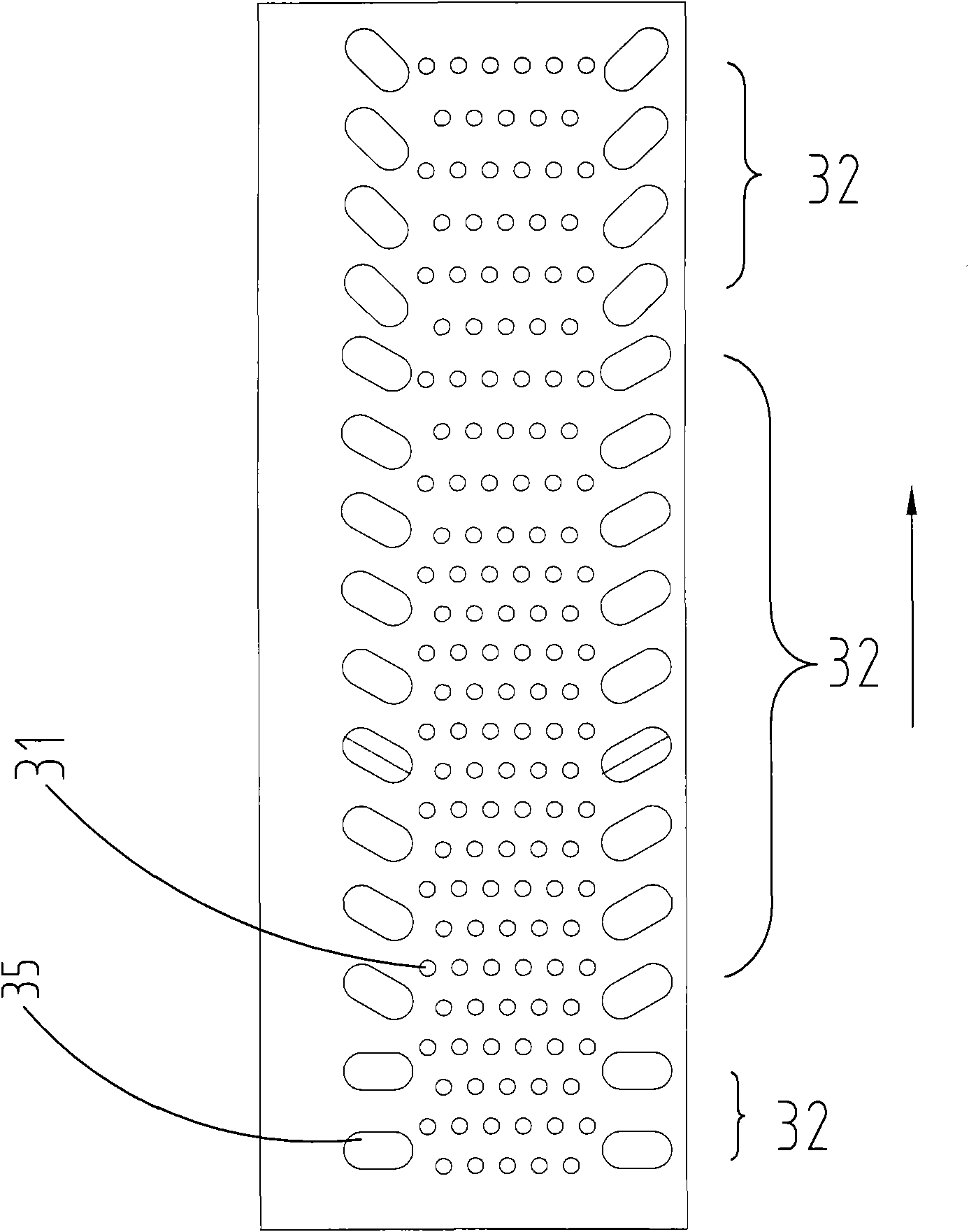
[0017] like Figures 1 to 3 As shown, the jet cooling device for a heat treatment furnace according to this embodiment includes a circulating fan 2 with an air inlet 21 and an air outlet 22, an air cooling chamber 1 whose upper part is communicated with the air inlet 21 of the circulating fan 2, and is arranged in the air cooling chamber 1. A carrier 8 for placing workpieces in the chamber 1, a heat exchanger 6 arranged in the air-cooled chamber 1 and located above the carrier 8, an air blower 3 arranged in the air-cooled chamber 1 and located above the carrier 8, both ends The first channel 4 communicated with the air outlet 22 of the circulating fan 2 and the air spray body 3 respectively, and the second channel 5 respectively communicated with the air outlet 22 of the circulating fan 2 and the bottom of the air cooling chamber 1 at both ends.

[0018] The bearing platform 8 divides the air-cooling chamber 1 into two upper and lower spaces, on which a conveyor belt 7 driven ...


PUM


Abstract

The invention discloses a jet cooling device for a heat treatment furnace. The jet cooling device comprises a circulating fan, an air-cooling chamber, a bearing table, a heat exchanger, an air jet body and a first passage, wherein the circulating fan is provided with an air inlet and an air outlet; the upper part of the air-cooling chamber is communicated with the air inlet of the circulating fan; the bearing table is arranged inside the air-cooling chamber and is used for bearing a workpiece; the heat exchanger is arranged inside the air-cooling chamber and is positioned above the bearing table; the air jet body is arranged inside the air-cooling chamber; two ends of the first passage are respectively communicated with the air outlet of the circulating fan and the air jet body; a plurality of air jet holes facing the bearing table are formed on the air jet body; and the distribution density of the air jet holes is gradually reduced from a feeding end to a discharging end. The jet cooling device has large air jet quantity at the feeding end and can improve the cooling speed of a front section of the workpiece.

Description

technical field [0001] The invention relates to a jet cooling device for a heat treatment furnace. Background technique [0002] For the existing jet cooling device for heat treatment furnace, see Chinese patent document "High-strength jet cooling device for pipes and bars", publication number: ZL200920095852.8, the cooling device includes a circulating fan and a heat exchanger arranged below the circulating fan, The upper and lower channels are respectively set on the left and right sides of the air outlet of the circulating fan, and a large amount of high-speed protective atmosphere is sprayed from the upper and lower channels to cool the workpiece, which can spray the workpiece up and down. The jet cooling device implemented in accordance with this patent cannot achieve the higher cooling rate requirement for the front section of the workpiece. SUMMARY OF THE INVENTION [0003] The technical problem to be solved by the present invention is to provide a jet cooling devi...

Claims


Application Information

Patent Timeline
Patent Type & Authority Applications(China)
IPC IPC(8): C21D1/62C21D1/613
Inventor 郑秀凤徐芳蒋岳明
Owner SUZHOU ZHONGMENZI TECH
Learn More