Process for synthesizing natural gas by methanation of coal synthesis gas

A coal-to-synthesis gas and chemical synthesis technology, which is applied in the petroleum industry, gas fuel, fuel, etc., can solve the problems of increasing equipment investment and achieve the effects of saving heat energy, increasing the selectivity of main products, and increasing the conversion rate of raw material gas

Inactive Publication Date: 2011-02-23
SEDIN ENG +1
View PDF7 Cites 55 Cited by
  • Summary
  • Abstract
  • Description
  • Claims
  • Application Information

AI Technical Summary

Problems solved by technology

Although the cycle compression power is slightly reduced, multiple methanation reactors are required for methanation reaction, which greatly increases equipment investment

Method used


Image

  • Process for synthesizing natural gas by methanation of coal synthesis gas
  • Process for synthesizing natural gas by methanation of coal synthesis gas
  • Process for synthesizing natural gas by methanation of coal synthesis gas

Examples


Embodiment 1

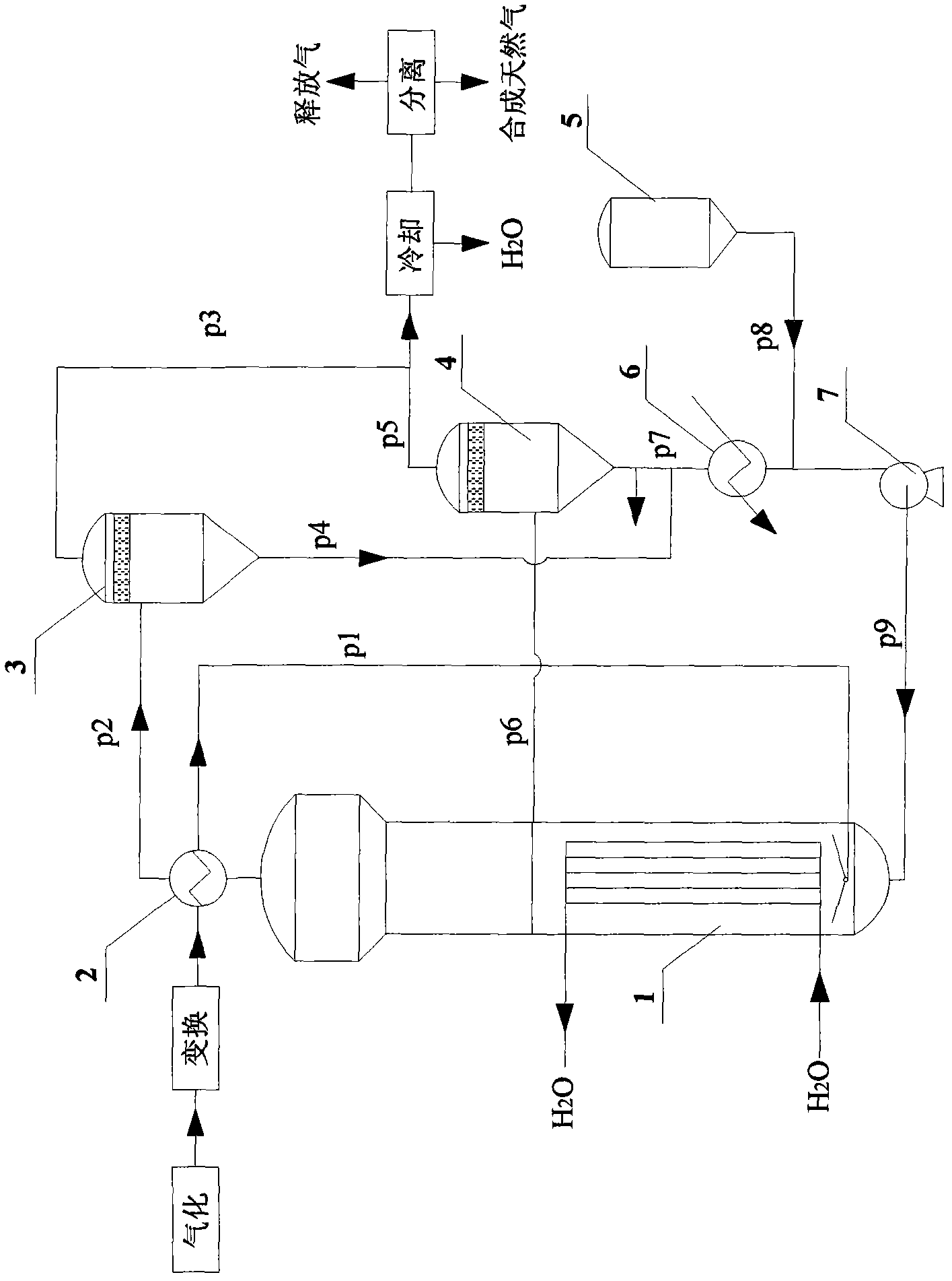
[0028] Coal is gasified to produce coal gas, which is then transformed into methanation raw material gas, which is composed of (V%): H 2 -65, CO-21, CO 2 -1,CH 4 -12. First, the domestic J101 type methanation catalyst dispersed in the inert liquid phase medium (the catalyst concentration in the liquid phase is 30 wt%) in the fresh catalyst storage tank 5 is pressed into the slurry bed methanation reactor 1 from the bottom through the circulation pump 7 , then the composition becomes H 2 -10mol% and N 2 -90mol% reducing gas is introduced from the bottom of slurry bed methanation reactor 1 through pipeline p1, and after the temperature is raised to 400°C at a heating rate of 1°C / min, the catalyst is reduced at normal pressure. The reducing gas is switched to methane raw material gas, and the pressure is raised to 3Mpa at the same time, the temperature is adjusted to the reaction temperature, and the methanation reaction is carried out in the slurry bed methanation reactor 1,...

Embodiment 2~11

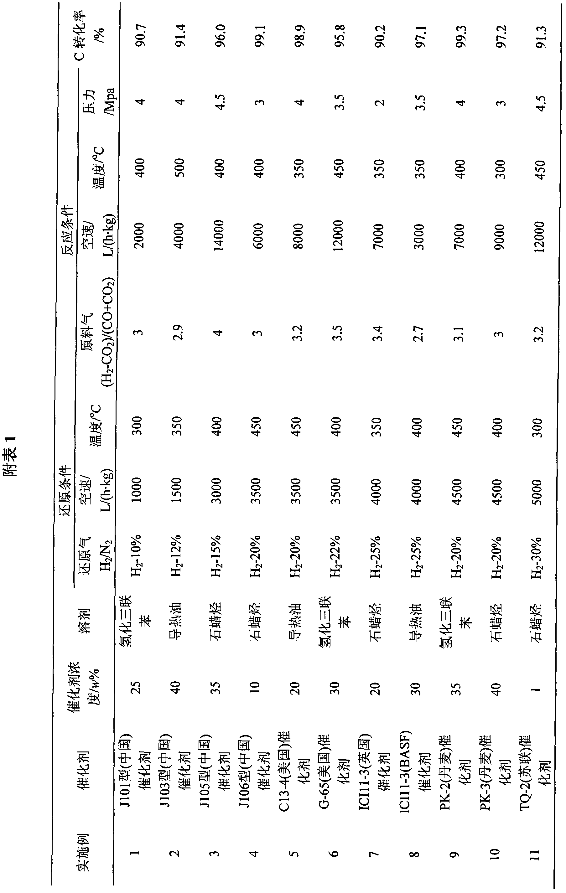
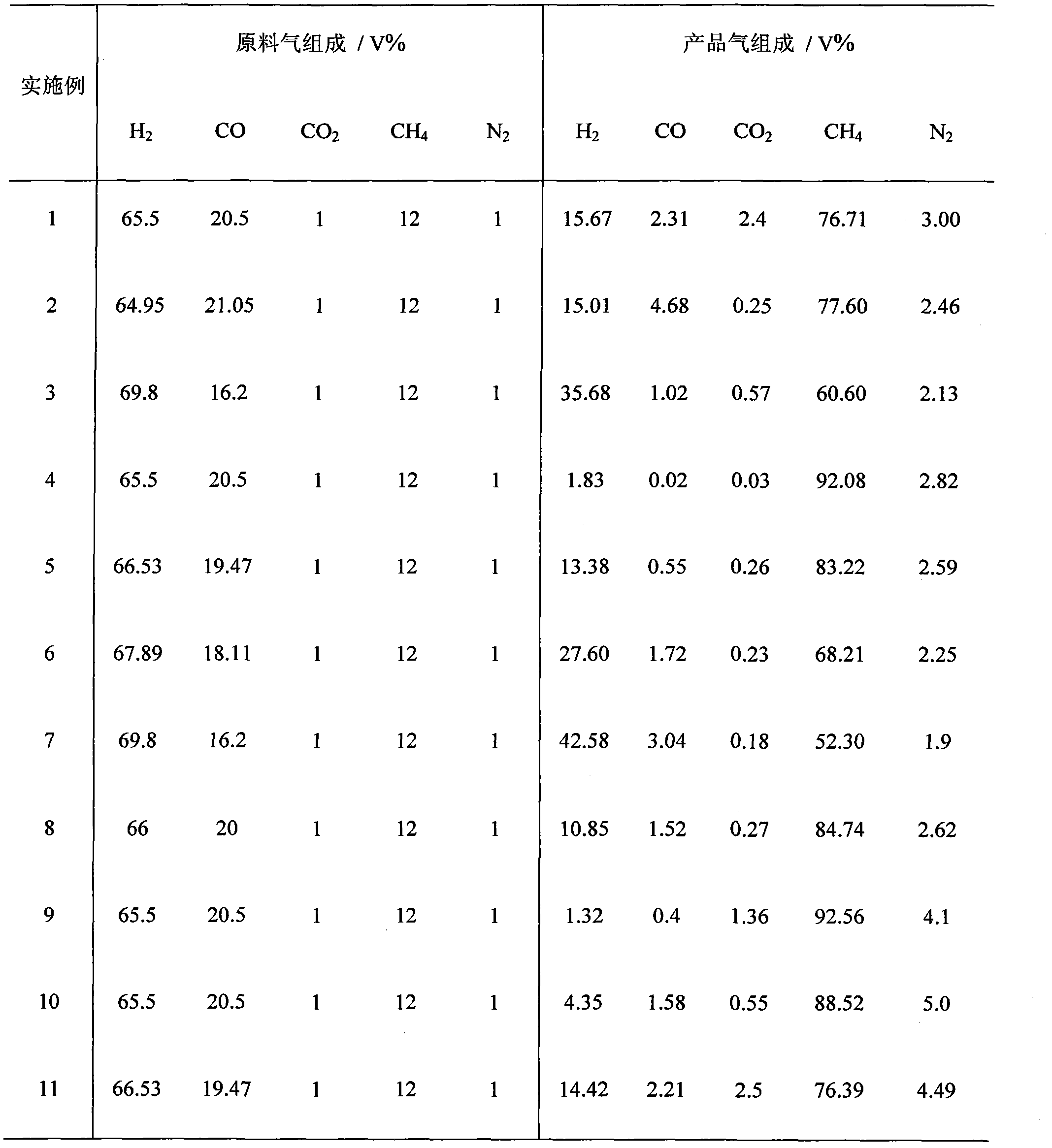
[0030]On the basis of Example 1, Examples 2-11 are about the catalyst type, the concentration of the catalyst in the slurry bed methanation reactor, the type of inert liquid medium, the composition of the reducing gas, the space velocity of the reducing gas, the reduction temperature, and the feed gas The hydrogen-carbon ratio, space velocity, reaction temperature, and reaction pressure factors have been adjusted. The specific data and results are shown in Attached Table 1, and the composition of raw material gas and product gas is shown in Attached Table 2.

[0031]

[0032] Schedule 2

[0033]


PUM


Abstract

The invention discloses a process for synthesizing natural gas by methanation of coal synthesis gas, which comprises the following steps of: dispersing a fresh methanation catalyst into an inert liquid medium, delivering the medium into a slurry bed methanation reactor to perform reduction, performing methanation reaction on the transformed methanation raw gas after the reduction is finished, delivering the tail gas to a gas-liquid separator I, discharging the slurry liquid component and the catalyst in the tail gas from the bottom of the gas-liquid separator I, discharging the gas phase in the tail gas from the top of the gas-liquid separator I, delivering partial slurry liquid component containing the catalyst into a gas-liquid separator II, discharging the gas phase from the top of thegas-liquid separator II, merging the gas phases discharged from the tops of the gas-liquid separators I and II, cooling and purifying the gas phases to obtain synthesized natural gas, discharging theslurry liquid component containing the catalyst from the bottom of the gas-liquid separator II, merging the slurry liquid component discharged from the bottom of the gas-liquid separator II and the slurry liquid component and the catalyst discharged from the bottom of the gas-liquid separator I, discharging 1 to 5 percent of the weight sum of the slurry liquid component and the catalyst separatedfrom the two gas-liquid separators, and performing methanation reaction on the cooled rest slurry liquid component and catalyst and the fresh methanation catalyst dispersed into the insert liquid medium together. The process has the advantages of low power consumption and low equipment investment, and is easy to operate.

Description

technical field [0001] The invention belongs to a process for synthesizing natural gas, in particular to a process for methanating coal-based syngas to synthesize natural gas. Background technique [0002] At present, the use of coal gasification synthesis gas to produce alternative natural gas has attracted extensive attention. H in coal gasification synthesis gas 2 , CO, CO 2 Carrying out methanation reaction can produce artificial natural gas, and the reaction formula is as follows: [0003] CO+3H 2 =CH 4 +H 2 O+206KJ / mol (1) [0004] CO 2 +4H 2 =CH 4 +2H 2 O+165KJ / mol (2) [0005] The methanation reaction is a strongly exothermic reaction under the action of a catalyst. In the usual gas composition, every 1 percent of CO methanation can produce an adiabatic temperature rise of 74 ° C; every 1 percent of CO 2 Methanation can produce an adiabatic temperature rise of 60°C. Therefore, it is necessary to control the temperature in the methanation reactor during ...

Claims


Application Information

Patent Timeline
Patent Type & Authority Applications(China)
IPC IPC(8): C10L3/08
Inventor 张庆庚李忠闫少伟崔晓曦范辉何忠郑华艳曹会博
Owner SEDIN ENG
Why Eureka
Try Eureka