
Multiple terminal cooperative communication method in cognition wireless network

A cognitive wireless network and cooperative communication technology, applied in the field of multi-terminal cooperative communication in cognitive wireless network, can solve the problems of low utilization rate of spectrum resources, neglect of spectrum sensing characteristics of intelligent terminals, single transmission mode, etc., and achieve energy consumption cost Minimize, increase the overall data transfer rate, control the effect of power consumption

Inactive Publication Date: 2011-02-16
BEIJING UNIV OF POSTS & TELECOMM
View PDF4 Cites 48 Cited by
  • Summary
  • Abstract
  • Description
  • Claims
  • Application Information

AI Technical Summary

Problems solved by technology

[0010] In short, the prior art has the following disadvantages: first, the application mode of the prior art only relies on a single transmission mode (direct transmission or relay transmission), does not make full use of the idle spectrum resources of the system, and its utilization rate of spectrum resources is low; Second, the existing technology does not introduce relevant theoretical knowledge of cognitive radio, ignoring the spectrum sensing characteristics of smart terminals; third, the existing technology does not consider power allocation from an economic point of view, and only maximizes system throughput from a purely technical point of view Or minimize system power consumption, which cannot well reflect the restrictive effect of price factors on power allocation

Method used


Image

  • Multiple terminal cooperative communication method in cognition wireless network
  • Multiple terminal cooperative communication method in cognition wireless network
  • Multiple terminal cooperative communication method in cognition wireless network

Examples


Embodiment Construction

[0031] In order to make the purpose, content, and advantages of the present invention clearer, the implementation manners of the present invention will be further described in detail below in conjunction with the accompanying drawings.

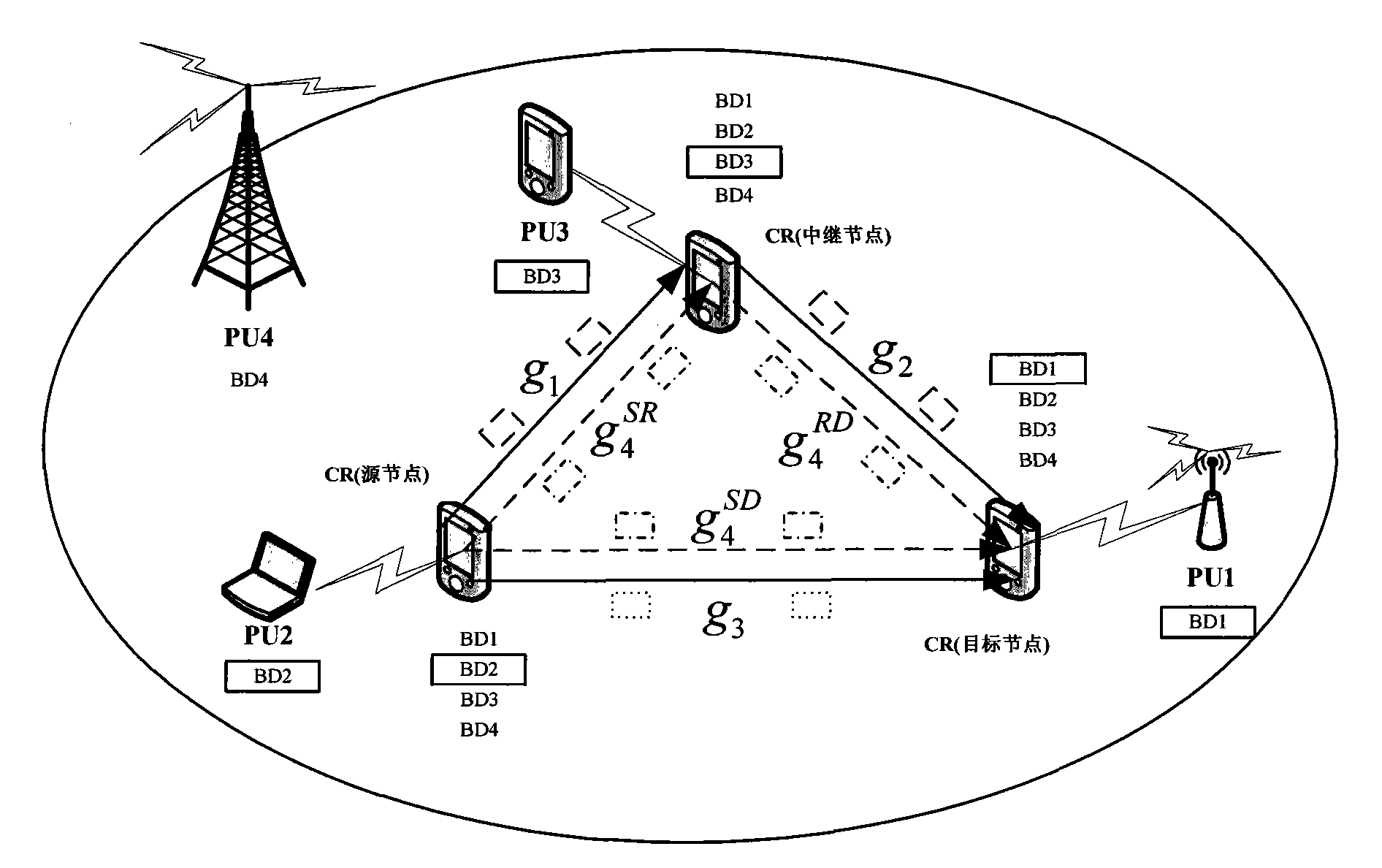
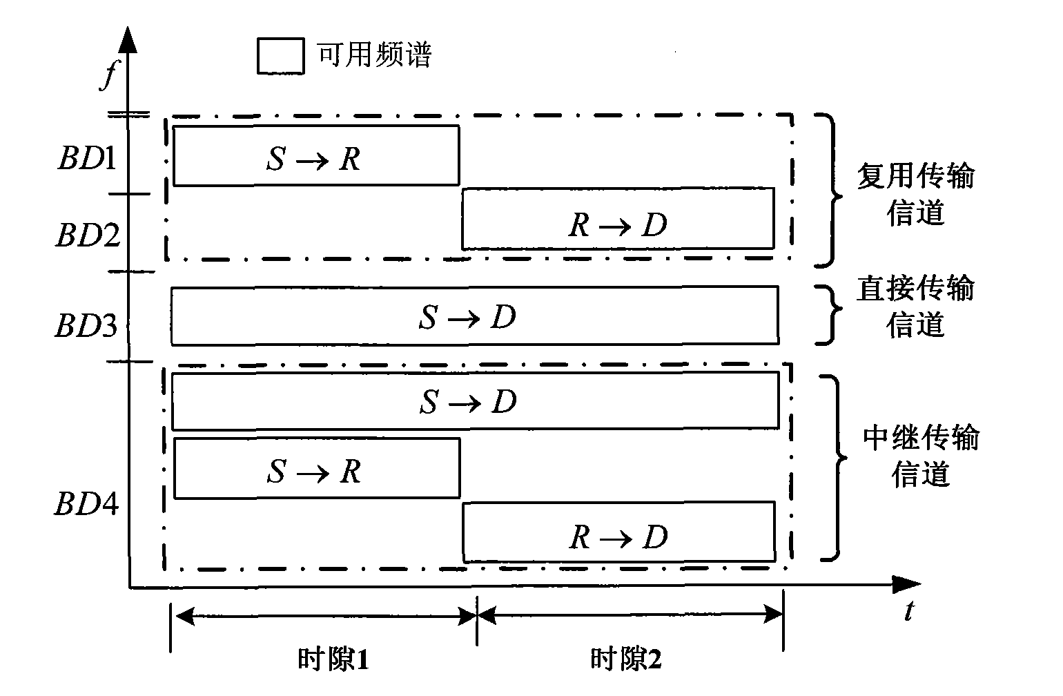
[0032] Combine below figure 2 , 3 and 4 explain method embodiments of the present invention.

[0033] Such as figure 2 Shown is the application network scenario diagram of this embodiment. The ones with boxes are the frequency bands in use, and the ones without boxes are the unused frequency bands. For example, for PU (primary user, primary user) 2, the frequency band used by it is BD2, where BD is an abbreviation of frequency band, which means a frequency band.

[0034] Such as Figure 4 Shown is the application network model diagram of this embodiment. include:

[0035]Reconfigurable physical layer interface: The deployment of the network needs to be based on a reconfigurable hardware platform. The deployment of the physical layer ...


PUM


Abstract

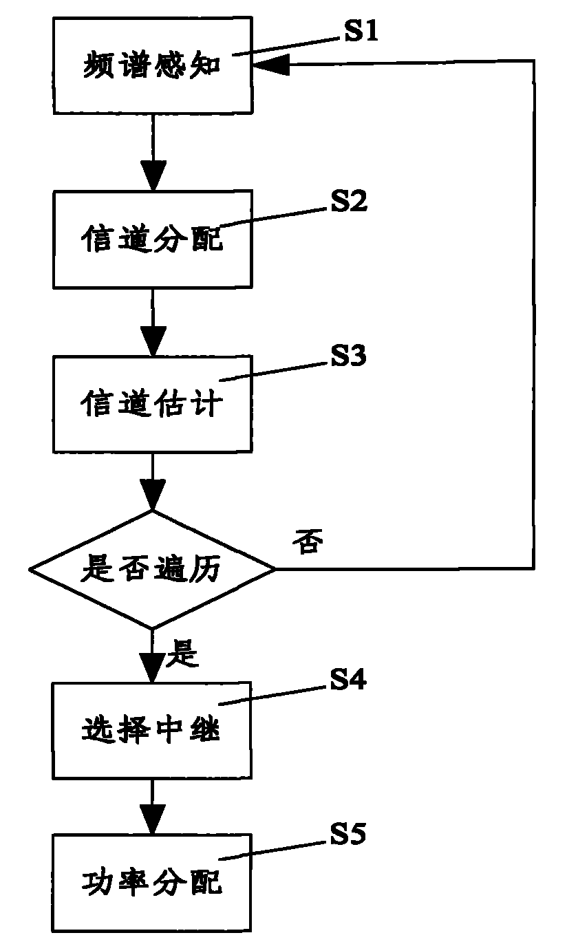
The invention discloses a multiple terminal cooperative communication method in a cognition wireless network, comprising the following steps: all source nodes, destination nodes and relay nodes are used for respectively determining currently available communication channels by spectrum sensing; the source nodes are used for selecting the relay nodes in a traversal manner and distributing a directtransmission channel, a multiplying channel and a relay transmission channel according to intersection characteristics of a perceptive available communication channel; channel estimation is carried out on the multiplying channel and the relay channel of the relay nodes according to channel allocation condition and equivalent signal to noise ratio and equivalent channel capacity are obtained according to a normalization channel capacity formula and the calculation results of the equivalent channel capacity are returned to the source nodes; the relay node with the largest equivalent channel capacity is selected as the optimal relay node for communicating with the source node and the destination node; and finally, transmitting power of the nodes in different channels are allocated. In the invention, service data can be sent by various transmission modes in a parallel manner, thus preferable QoS guarantee can be provided for the network, power consumption is reduced and network survival time is lengthened.

Description

technical field [0001] The invention relates to the technical field of wireless network communication, in particular to a multi-terminal cooperative communication method in a cognitive wireless network. Background technique [0002] Spectrum resource is a non-renewable resource, how to improve spectrum utilization and realize dynamic spectrum management has become an urgent problem to be solved. According to FCC (Federal Communications Commission) statistics, in 2002, the spectrum utilization rate below 3GHz was only 5.2%. In 2005, SSC (Shared Spectrum Company) monitored 30 frequency bands from 30MHz to 2.9GHz, and found that the average occupancy rate of the spectrum was only 6%, and the highest instantaneous occupancy rate was only 17%. This shows that there are many spectrum resources that are not utilized, which leads to a problem: in complex and changeable cognitive wireless networks, how to efficiently use limited spectrum resources to provide users with high-quality ...

Claims


Application Information

Patent Timeline
IPC IPC(8): H04W24/00H04W28/16H04L25/02H04W52/04H04L12/54
Inventor 胡铮张平张国翊李耿宇王灿如田辉苗杰
Owner BEIJING UNIV OF POSTS & TELECOMM
Learn More