
Method for QoS delay detection in communication system

A communication system and time-delay technology, which is applied in the field of electrical communication, can solve the problems of not being able to provide QoS classification data flow delay basis, not being able to distinguish QoS data flow, etc., and achieve the effect of real-time guarantee

Inactive Publication Date: 2007-12-26
HUAWEI TECH CO LTD
View PDF5 Cites 0 Cited by
  • Summary
  • Abstract
  • Description
  • Claims
  • Application Information

AI Technical Summary

Problems solved by technology

However, this method cannot provide the delay basis for QoS-related classified data streams, because it cannot distinguish different types of QoS data streams, and the Ping message can only be applied to the IP layer, and can only perform delay tests on a single data stream. It is not possible to classify data flows for each QoS

Method used


Image

  • Method for QoS delay detection in communication system
  • Method for QoS delay detection in communication system

Examples


Embodiment Construction

[0025] The invention provides a method for obtaining the time delay of QoS-related classified data flow in a communication system, so that the communication system can test the performance requirement of QoS.

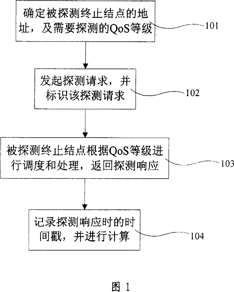
[0026] As shown in Figure 1, it is a flow chart of an embodiment of the QoS delay detection method initiated by the detected node in the communication system of the present invention, including the following steps:

[0027] Step 101, the detected start node determines the address of the detected end node and the QoS level to be detected;

[0028] Step 102: The probed start node sends a predefined probe request message to the probed end node. The probe request message includes: the time stamp when the probe was initiated, the address of the originator, the destination address, and the QoS probe index, and identifies The probe request is a data packet of the QoS level;

[0029] Step 103: After receiving the probe request, the detected termination node performs scheduling...


PUM


Abstract

The present invention relates to a QoS time delay detection method in communication system. It contains the detected initial node determining detected ending node address and require detected QoS grade; detected initial node originating detection request to detected end node and labeling said detection request as said QoS grade data package; detected end node receiving detection request and according to QoS grade to make scheduling and processing, feeding back detection responding to detected initial node; detected initial node receiving detection responding and recording detection responding time stamping to make calculation to make calculation. Said method defines a method for obtaining QoS correlation classified data stream time delay in communication system, to make communication system capable of test QoS performance requirement, net element capable of selecting more suitable way transferring data package to obtain preferable QoS ensuring.

Description

technical field [0001] The invention relates to the technical field of electrical communication, in particular to a method for detecting QoS time delay in a communication system. Background technique [0002] In communication systems, such as WiMax, WCDMA, GPRS, and other fixed or mobile communication systems related to IP packet services, including Internet networks, when it is necessary to select the target base station for handover, the path of data flow, and the network or network entity served When , it is often necessary to consider the delay characteristics of various networks or network entities, so as to obtain better QoS services. [0003] At present, among the protocols of the communication system, only the IP protocol has a Ping (Packet Internet Grope, Internet packet explorer) message, which can simply test the delay of the network. The Ping command sends an ICMP (Internet Control Message Protocol, Internet Control Message Protocol) echo request message to the ...

Claims


Application Information

Patent Timeline
Patent Type & Authority Patents(China)
IPC IPC(8): H04L12/26H04L12/56H04L45/741
Inventor 周艳
Owner HUAWEI TECH CO LTD
Learn More