Zero temperature coefficient optical wave plate and polarization state converter

A temperature coefficient and polarization state technology, applied in the direction of optical waveguide light guide, optical waveguide coupling, instrument, etc., can solve the problems of not making full use of the best function of the system, wave plate delay phase deviation, adding additional noise, etc., to reduce the system cost, improve work efficiency, and simplify the system structure

Active Publication Date: 2011-02-16
CHINA ELECTRIC POWER RES INST +1
View PDF38 Cites 5 Cited by
  • Summary
  • Abstract
  • Description
  • Claims
  • Application Information

AI Technical Summary

Problems solved by technology

The latter method even artificially makes the delay phase of the wave plate deviate from the ideal value, artificially makes the system in a non-optimal working state, and artificially increases the resulting additional noise
Therefore, these three methods all sacrifice the best scale factor S obtained when the fiber waveplate has an ideal delay phase opt At the expense of the best features of the system, such as linear range, signal-to-noise ratio, etc.
[0031] From the above description, it can be known that there is no fiber wave plate whose delay phase is not affected by temperature changes; if the delay phase of the fiber wave plate is not affected by temperature changes, one of the two factors that affect the performance of the above system will be completely eliminated. Excluded, the existing complex methods of compensating the measurement error caused by the delay phase change of the wave plate are not necessary to adopt

Method used


Image

  • Zero temperature coefficient optical wave plate and polarization state converter
  • Zero temperature coefficient optical wave plate and polarization state converter
  • Zero temperature coefficient optical wave plate and polarization state converter

Examples


Embodiment 1

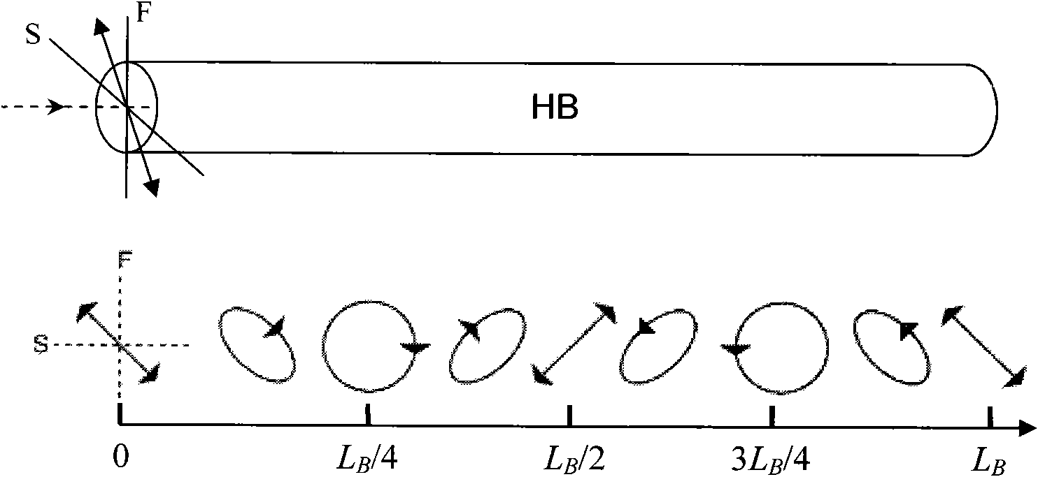
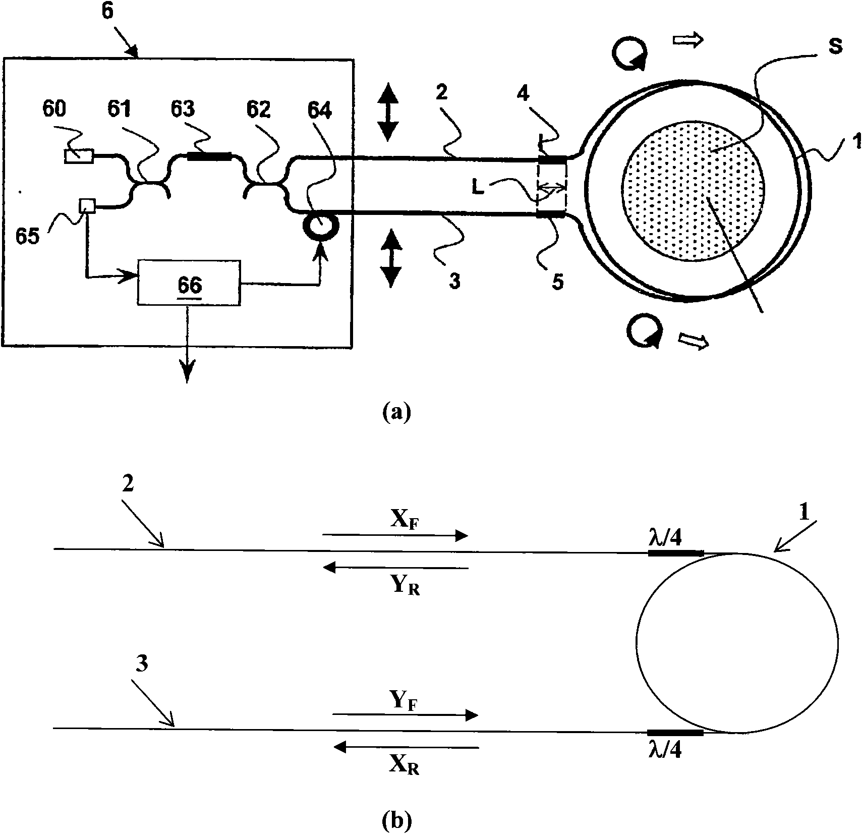
[0080] Image 6 It is the basic embodiment 1 according to the method of the present invention, wherein (a) is a schematic structural view of a fiber wave plate or a fiber polarization state converter (collectively referred to as FWP) of the present invention, and (b) is a fast axis and a slow axis of the FWP relative to the incident light Orientation diagram of X and Y polarization directions. Image 6 In (a), HB1 is the length L 1 A section of HiBi fiber, the thermal expansion coefficient of the fiber is K L1 , the beat length is L B1 , the temperature coefficient of the beat length is K B1 ;HB2 is the length L 2 Another HiBi fiber, the thermal expansion coefficient of the fiber is K L2 , the beat length is L B2 , the temperature coefficient of the beat length is K B2 . The fast axis of HB2 is welded perpendicular to the fast axis of HB1 to form a length L=L 1 +L 2 FWP (the arrangement of HB1 and HB2 is in no particular order).

[0081] A beam of linearly polarized...

Embodiment 2

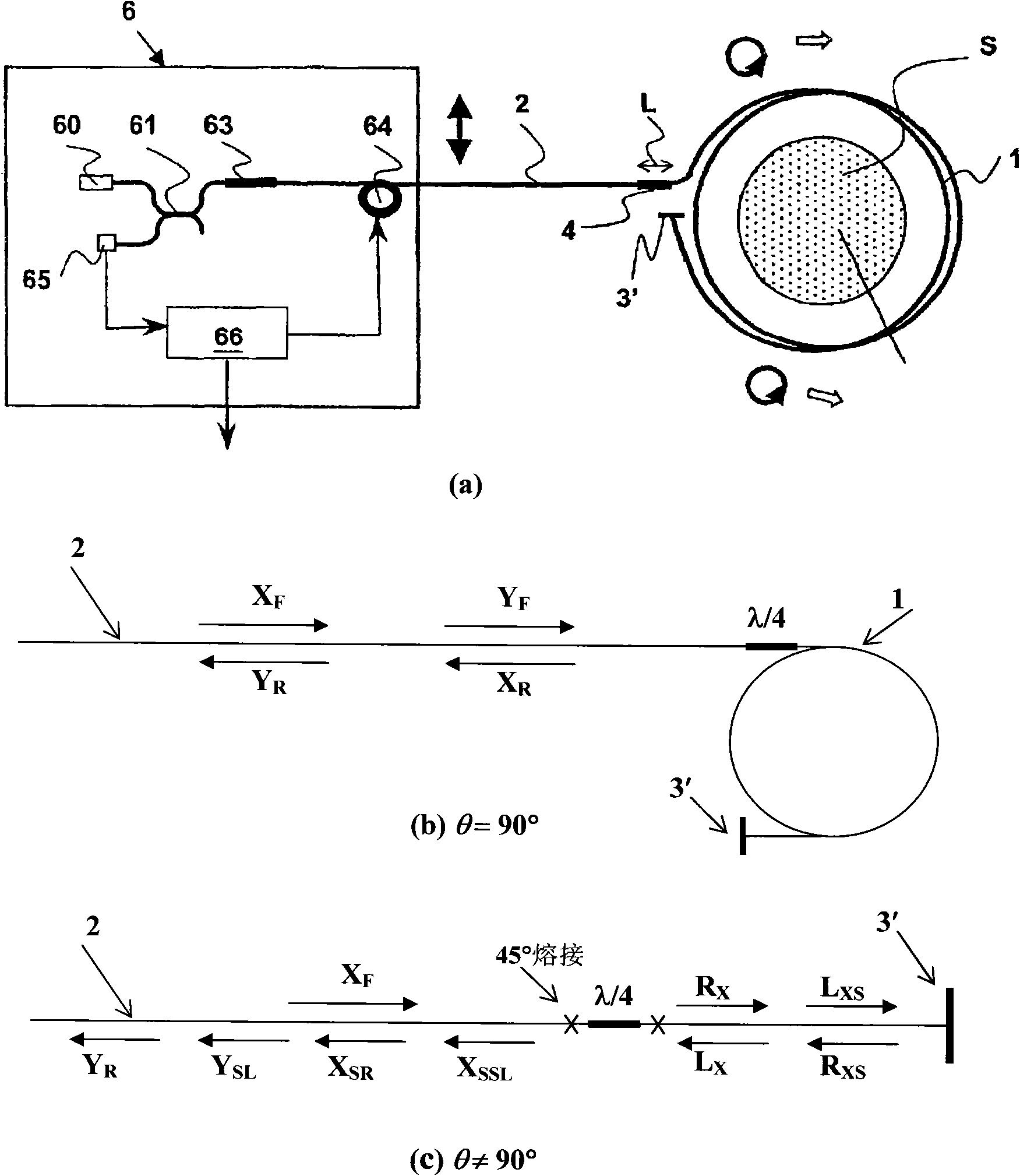
[0133] Figure 7 It is the basic implementation of the temperature complementary FWP according to the method of the present invention, wherein (a) is a structural schematic diagram of this FWP, and (b) is an orientation diagram of the fast axis and the slow axis of the FWP relative to the X and Y polarization directions of the incident light. Figure 7 In (a), HBp is the length L p A section of HiBi fiber, the thermal expansion coefficient of the fiber is K Lp , the beat length is L Bp , the temperature coefficient of the beat length is K Bp ≥0; HBn is the length L n Another HiBi fiber, the thermal expansion coefficient of the fiber is K Ln , the beat length is L Bn , the temperature coefficient of beat length is (-K Bn )ρ +L n The temperature complementary FWP (HBp, HBn in no particular order).

[0134]Imitate the analysis of embodiment 1, at this moment

[0135] θ = φ p + φ n ...

Embodiment 3

[0168] Figure 8 According to the basic embodiment 2 of the present invention, wherein BC1 is a kind of positive crystal (or negative crystal) birefringent optical medium whose thickness is L1 on the direction of light propagation, and BC2 is another kind of positive crystal whose thickness is L2 on the direction of light propagation (or negative crystal) birefringent optical medium, the optical axes of BC1 and BC2 are perpendicular to each other, and both are perpendicular to the direction of light propagation. When L1 and L2 meet the requirements of formula (11), (12), or (11-1), (12-1), or (11-2), (12-2), the delay phase composed of BC1 and BC2 A wave plate of θ has a temperature coefficient of zero.


PUM


Abstract

The invention provides multiple zero temperature coefficient optical wave plates or optical wave polarization state converters. The optical wave plate or optical wave polarization state converter is formed by the way that two refractive optical mediums HB1 and HB2 the fast axes of which are mutually vertical or parallel are welded or connected together. The length of HB1 is L1, beat length is LB1, temperature coefficient of beat length is KB1, phase delay of linear polarized light the polarization direction of which is respectively parallel with fast axis and slow axis of HB1 after passing through HB1 is Phi1; the length of HB2 is L2, beat length is LB2, temperature coefficient of beat length is KB2, phase delay of linear polarized light the polarization direction of which is respectivelyparallel with fast axis and slow axis of HB2 after passing through HB2 is Phi2; the length of optical wave plate and optical wave polarization state converter formed by HB1 and HB2 according to the method is L which is equal to L1+L2, and phase delay theta is Phi1-Phi2 or Phi1+Phi2. When KB1 is different from KB2, the optical wave plate and optical wave polarization state converter designed according to the method provided by the invention have phase delay theta with the temperature coefficient of zero.

Description

technical field [0001] The invention belongs to the field of sensitive electronics and sensors in electronics and information systems, and the field of high voltage and large current measurement in electrical engineering, and specifically relates to various optical wave plates with zero temperature coefficients, especially optical fiber wave plates, such Waveplates are suitable for various optical systems that need to analyze and control the polarization state of light, such as various optical fiber sensors, various all-fiber optical or photoelectric measurement systems, etc. In such an optical or optoelectronic system, such an optical wave plate can be used as an optical polarization state converter, an optical polarization plane rotator, an optical isolator, a variable beam splitter, an optical attenuator, and an optical switch. Wait. Background technique [0002] Waveplates are widely used in various optical systems that need to analyze and control the polarization state...

Claims


Application Information

Patent Timeline
Patent Type & Authority Applications(China)
IPC IPC(8): G02B6/10G01R19/00G02B6/26G02B6/14
Inventor 陈祥训陈硕雷林绪刘占元尹树杰
Owner CHINA ELECTRIC POWER RES INST
Why Eureka
Try Eureka