
Method for preparing isolated supporting point array between vacuum glass substrates by screen printing

A technology of vacuum glass and screen printing, which is applied in glass forming, glass reshaping, glass production, etc. It can solve the problems of loss of vacuum glass effect, complicated manufacturing process, and time-consuming stacking, so as to improve the aesthetics and simplify the process. , the effect of low production cost

Inactive Publication Date: 2011-02-16
BEIJING INSTITUTE OF GRAPHIC COMMUNICATION
View PDF1 Cites 24 Cited by
  • Summary
  • Abstract
  • Description
  • Claims
  • Application Information

AI Technical Summary

Problems solved by technology

The vacuum glass manufactured by this method has micro-cracks during use due to the brittleness of the organic adhesive in the cold winter or the inherent aging defects of the organic adhesive, which leads to air leakage and loses the effectiveness of the vacuum glass.
[0007] In addition, whether it is metal or polymer isolation supports, because the isolation supports are thin and numerous, it takes time to stack and fix, and the manufacturing process is complicated.

Method used


Image

  • Method for preparing isolated supporting point array between vacuum glass substrates by screen printing
  • Method for preparing isolated supporting point array between vacuum glass substrates by screen printing
  • Method for preparing isolated supporting point array between vacuum glass substrates by screen printing

Examples


Embodiment 1

[0031] (1) Cut, edge and clean the original glass plate according to the required size. The original glass plate can be ordinary float glass, tempered glass, various coated glass, self-cleaning glass, low-emissivity glass, high visible light transmittance glass and so on.

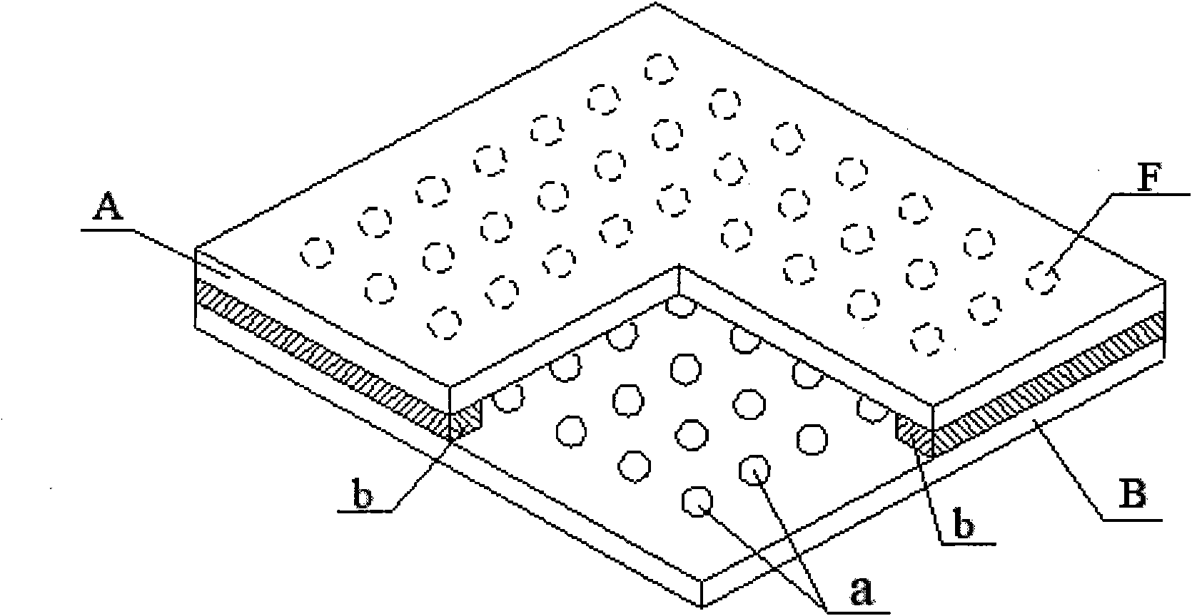
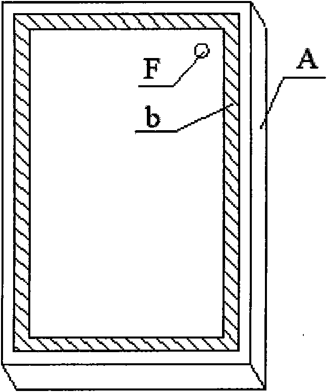
[0032] (2) Use a mechanical drill or a laser drilling machine to make an exhaust hole with a diameter of 2mm on a glass plate. This glass is called the front substrate glass A, and the other glass is called the rear substrate glass B accordingly.

[0033] (3) Make isolation support points on the rear glass substrate by screen printing method. A rheological slurry suitable for screen printing is prepared by using amorphous low-melting glass powder M with a thermal expansion coefficient slightly smaller than that of the glass panel and an organic solution. Then use the screen printing method to print a lattice of cylindrical dots with a diameter of about 0.5mm and a thickness of about 25-35μm on the rear sub...

Embodiment 2

[0040] (1) Cut, edge and clean the original glass plate according to the required size. The original glass plate can be ordinary float glass, tempered glass, various coated glass, self-cleaning glass, low-emissivity glass, high visible light transmittance glass and so on.

[0041] (2) Use a mechanical drill or a laser drilling machine to make a vent hole with a diameter of 1mm on a glass plate. This piece of glass is called the front substrate glass. Correspondingly, the other piece of glass is called the rear substrate glass.

[0042] (3) Make isolation support points on the rear substrate glass by screen printing. Use amorphous low-melting glass powder M with a thermal expansion coefficient slightly smaller than that of the glass panel and an organic solution to prepare a rheological slurry suitable for screen printing. Then use the screen printing method to print a dot matrix formed by wet film cylindrical dots with a diameter of about 0.5mm and a thickness of about 230-24...

Embodiment 3

[0049] (1) Cut, edge and clean the original glass plate according to the required size. The original glass plate can be ordinary float glass, tempered glass, various coated glass, self-cleaning glass, low-emissivity glass, high visible light transmittance glass and so on.

[0050] (2) Use a mechanical drill or a laser drilling machine to make a vent hole with a diameter of 3mm on a glass plate. This glass is called the front substrate glass A, and the other glass is called the rear substrate glass B accordingly.

[0051] (3) Make isolation support points on the rear substrate glass by screen printing. Use amorphous low-melting glass powder M with a thermal expansion coefficient slightly smaller than that of the glass panel and an organic solution to prepare a rheological slurry suitable for screen printing. Then use the screen printing method to print a dot matrix formed by wet film cylindrical dots with a diameter of about 0.5mm and a thickness of about 135-145μm on the rear...


PUM


Abstract

The invention discloses a method for preparing an isolated supporting point array between front and rear vacuum glass substrates by using screen printing equipment. The method comprises the following steps of: preparing low-melting glass powder into screen printing size, printing on the front glass substrate by using screen printing, and preparing the isolated supporting point array between vacuum glass panels by drying, sintering and other processes, wherein the diameter of each cylindrical point is 0.1 to 1.0mm; the thickness is 20 to 250 mu m; and longitudinal and transverse spacing between the points is 20 to 100mm. A sealing layer for sealing the edges of the vacuum glass is prepared on the rear glass substrate; the softening temperature of the used low-melting glass powder is 3 to 30 DEG C lower than that of the low-melting glass powder for preparing the supporting point array; and the thickness of the isolated supporting point is 1 to 20 mu m higher than that of the sealing layer on the edges of the vacuum glass. Under the action of the sealing temperature of the sealing layer on the edges of the vacuum glass and clamp pressure, the deformation of a supporting point sintered body is slightly lower than that of a sintered body on the edges of the sealing layer, and each supporting point in the supporting point array can be contacted with the front and rear glass substrates and is uniformly stressed on the premise of realizing edge airtight seal on the edges.

Description

Technical field [0001] The invention relates to a method for preparing an array of isolation support points between vacuum glass substrates by screen printing. Vacuum glass refers to the relative placement of two or more pieces of glass with intervals, and a number of tiny isolation support points are set between the glass pieces to form a point array. After exhaust sealing, the gap between the glass pieces A vacuum airtight cavity is formed to obtain a transparent flat material with excellent heat insulation and sound insulation performance. It is used in various technical fields such as doors and windows of buildings and transportation vehicles, and observation windows of refrigerated appliances. The invention mainly relates to a new method for preparing isolation support lattices between vacuum glass substrates. Background technique [0002] At present, the structures related to vacuum glass in the known technology are basically similar. figure 1 It is a typical vacuum...

Claims


Application Information

Patent Timeline
IPC IPC(8): C03B23/24
CPCY02P40/57
Inventor 许文才罗世永张新林
Owner BEIJING INSTITUTE OF GRAPHIC COMMUNICATION
Learn More