Suspension uni-directional/bi-directional steam catapult

A catapult and steam technology, applied in the direction of launch/drag transmission, etc., can solve the problems of slow take-off of fighters, frequent replacement of U-shaped sealing strips, high maintenance costs, etc. compact effect

Inactive Publication Date: 2011-02-16
李广
View PDF5 Cites 0 Cited by
  • Summary
  • Abstract
  • Description
  • Claims
  • Application Information

AI Technical Summary

Problems solved by technology

Old-fashioned catapults use rubber bands set on both sides of the cylinder opening to form a "zipper" seal, while active catapults use a U-shaped sealing strip to fill the opening of the cylinder. No matter which method is used, the maintenance cost is high. , the U-shaped sealing strip is frequently replaced and very troublesome, and has high requirements on the material; although it is no problem to meet the needs of the aircraft to take off, it is impossible to achieve the same degree of sealing as the cylinder of the steam engine, so every time it is ejected, it will A stream of high-temperature white smoke diffused from below the deck, which was leaking high-temperature, high-pressure steam, which not only consumed a lot of fresh water, but also wasted a lot of energy
The biggest problem with the steam catapult is that it cannot increase the speed and strength at the same time, and it cannot achieve the best cooperation and work, which makes the fighter take off slowly
It is precisely because of the above problems that the U.S. Navy is actively developing a more reliable steam catapult, but it has not been successful yet

Method used


Image

  • Suspension uni-directional/bi-directional steam catapult
  • Suspension uni-directional/bi-directional steam catapult
  • Suspension uni-directional/bi-directional steam catapult

Examples


Embodiment Construction

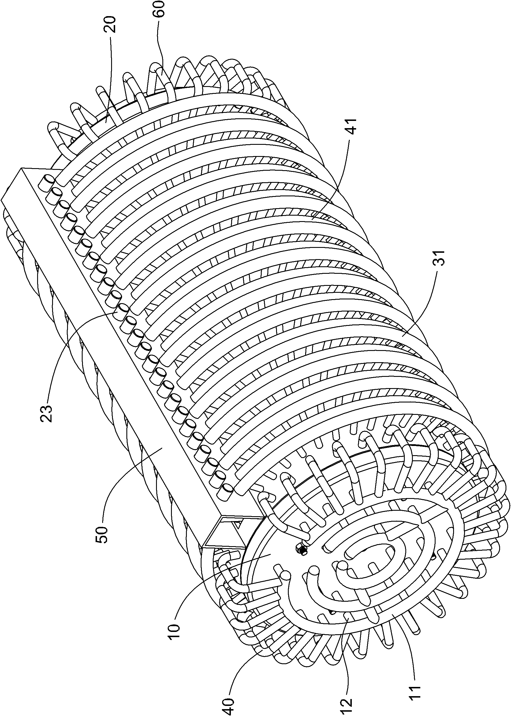
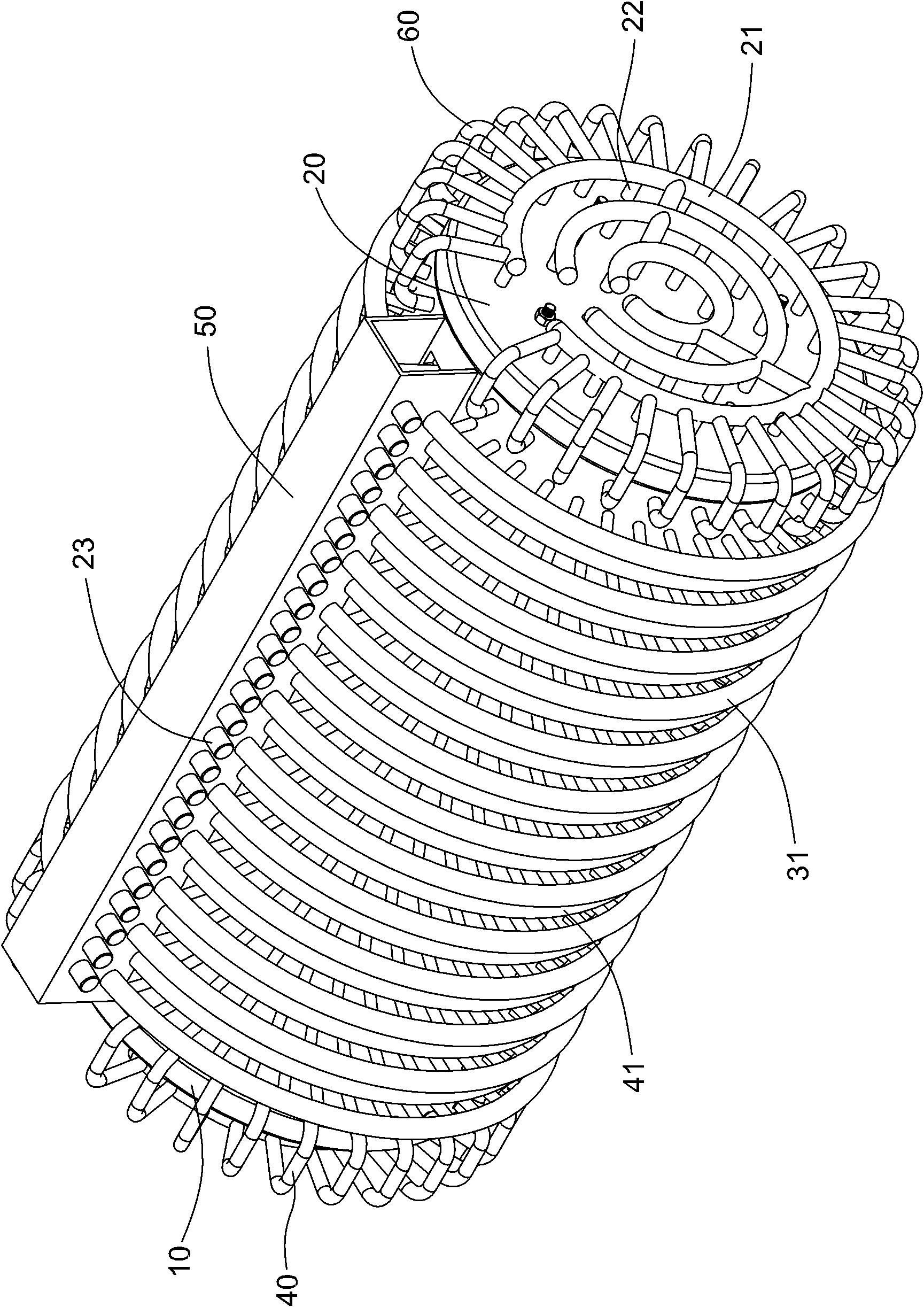
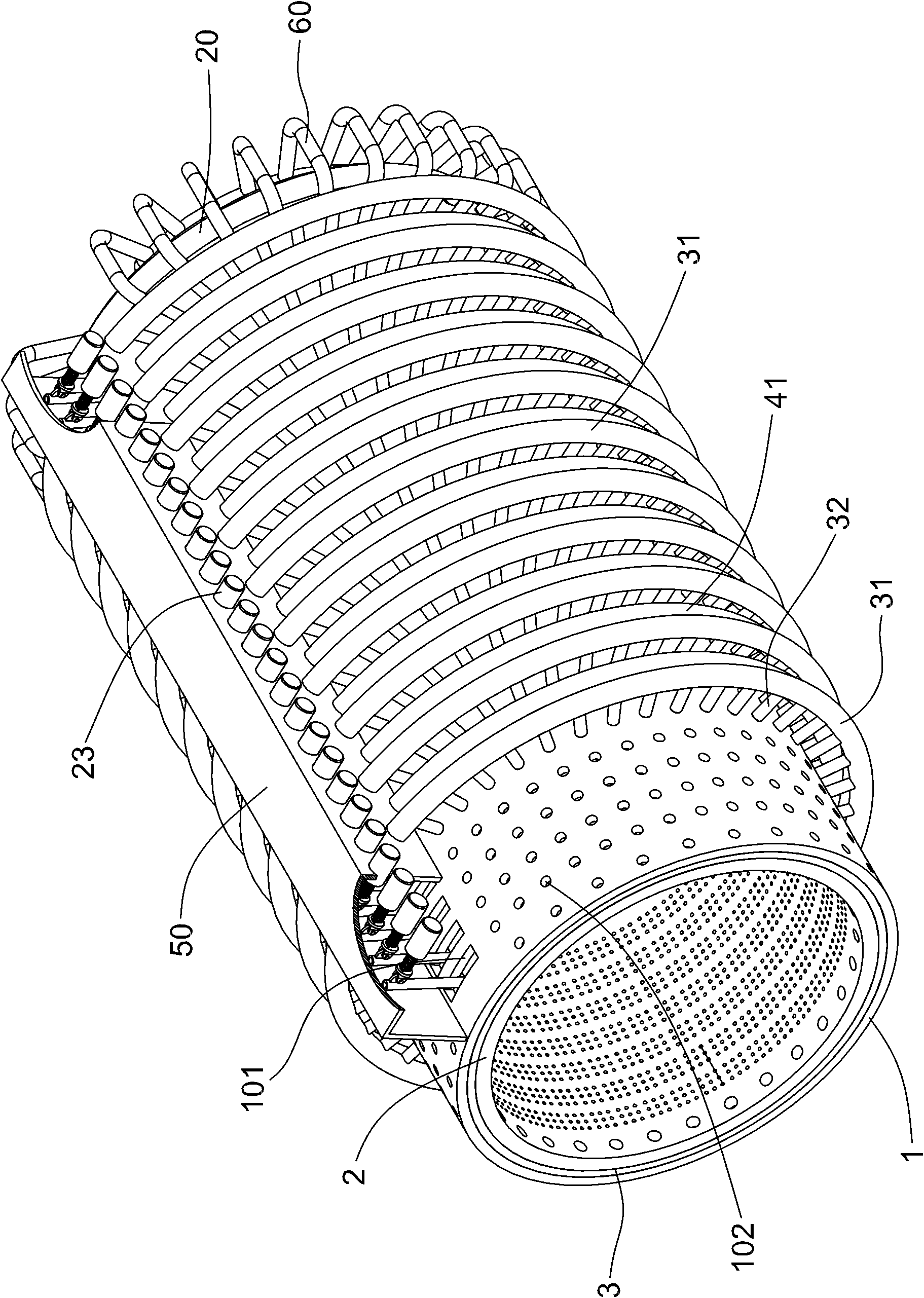
[0030] Label in the figure

[0031] 1 outer cylinder 101 outer long slot 102 steam port 103 steam distribution cavity

[0032] 2 Inner barrel 202 micro steam hole 203 big steam hole 204 big steam hole

[0033] 3 left end ring 301 large steam hole 4 right end ring 401 large steam hole

[0034] 5 control ring 501 screw hole 502 micro steam hole

[0035] 8 left tunnel pipe 9 right tunnel pipe

[0036] 10 Left cylinder head 11 Left steam pipe 12 Short pipe

[0037] 13 Suspension bar 14 Control rod 141 Ear plate 142 Bolt hole

[0038] 15 signal axis

[0039] 16 Left buffer 17 Right buffer 18 Sealed bearing seat 19 Sealed bearing seat

[0040] 20 Right cylinder head 21 Right steam pipe 22 Short pipe

[0041] 23 solenoid valve 24 valve stem 25 return spring 26 ear seat

[0042] 27 pin shaft 28 left steel cable 29 right steel cable

[0043] 30 Piston 31 Steam pipe

[0044] 32 short tube 33 mandrel 34 spacer 35 permanent magnetic ring

[0045] 36 insulating tube 37 slider 38...


PUM


Abstract

The invention discloses a suspension uni-directional / bi-directional steam catapult which comprises a cylinder, a left cylinder cover, a right cylinder cover, a piston, a steam guide pipe system, a left steel cable and a right steel cable; the cylinder consists of an outer cylinder and an inner cylinder; the left cylinder cover and the right cylinder cover are fixedly connected with the left and right ends of the outer cylinder respectively; multiple rows of annularly arranged steam ports are formed on the outer wall of the outer cylinder; through micro-steam holes are formed on the wall of the inner cylinder; the steam guide pipe system is composed of four groups of pipe collection; the first and second groups of pipe collections are arranged on the outer parts of the left and right cylinder covers respectively; the third and fourth groups of pipe collections are arranged on the outer wall of the outer cylinder; the piston is arranged in the inner cylinder; multiple suspension levers are arranged in the inner cylinder; the piston and the suspension levers are in sliding fit; a left tunnel pipe and a right tunnel pipe are mounted on the axle centre of the piston; the right side of the piston is fixedly connected with a signal shaft; and a left buffer and a right buffer are arranged on the inner sides of the left and right cylinder covers respectively. In the catapult, totally-closed cylinders are adopted; and the catapult has the advantages of compact structure, high airtight performance and heat energy utilization rate, large catapult force and high speed and can enable a heavy airplane to take off immediately.

Description

technical field [0001] The invention relates to an aircraft steam catapult used on an aircraft carrier, in particular to a suspended one-way and two-way steam catapult. Background technique [0002] If an airplane wants to take off from an aircraft carrier, it must rely on the thrust generated by a steam catapult. The steam catapult was invented by the British, but so far, only the Americans have produced a steam catapult that can be used in actual combat. The main body of the steam catapult is a large reciprocating cylinder, which converts steam energy into kinetic energy for ejection. High-temperature and high-pressure steam is produced by the ship's propulsion boiler and stored in the pressure storage tank. The input and pressure regulation of the steam in the pressure storage tank are controlled by valves. The steam catapult currently in service on the US aircraft carrier uses a slotted cylinder with a piston inside the cylinder. The piston needs to pass through the cyl...

Claims


Application Information

Patent Timeline
IPC IPC(8): B64F1/06
Inventor 李广
Owner 李广
Why Eureka
Try Eureka