
System-on-chip driver of high-subdivision multi-path stepping motor

A stepper motor, system-on-chip technology, applied in control systems, motor generator control, electrical components, etc., can solve the problems of low-frequency oscillation and high-frequency output, unable to meet the coordinated simultaneous operation of multiple stepper motors, etc., to reduce area, improve dynamic performance and motion position control accuracy, reduce system cost and power consumption

Inactive Publication Date: 2011-02-09
HARBIN INST OF TECH
View PDF4 Cites 27 Cited by
  • Summary
  • Abstract
  • Description
  • Claims
  • Application Information

AI Technical Summary

Problems solved by technology

[0009] In order to solve the problems of low-frequency oscillation and insufficient high-frequency output of current stepping motors, and the inability to satisfy the coordination and simultaneous operation of multiple stepping motors, the present invention provides a high-subdivision multi-channel stepping motor system-on-chip driver

Method used


Image

  • System-on-chip driver of high-subdivision multi-path stepping motor
  • System-on-chip driver of high-subdivision multi-path stepping motor
  • System-on-chip driver of high-subdivision multi-path stepping motor

Examples


specific Embodiment approach 1

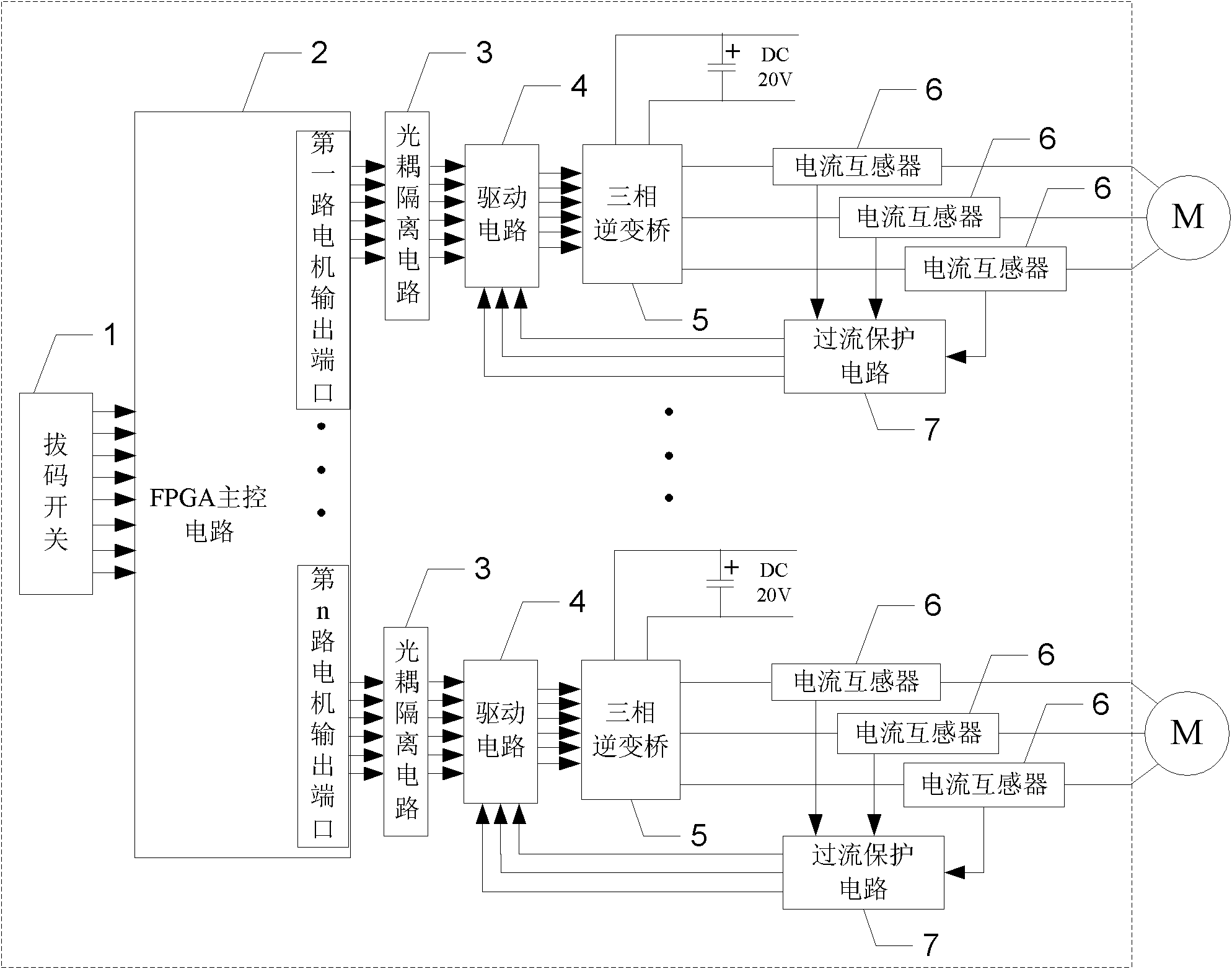
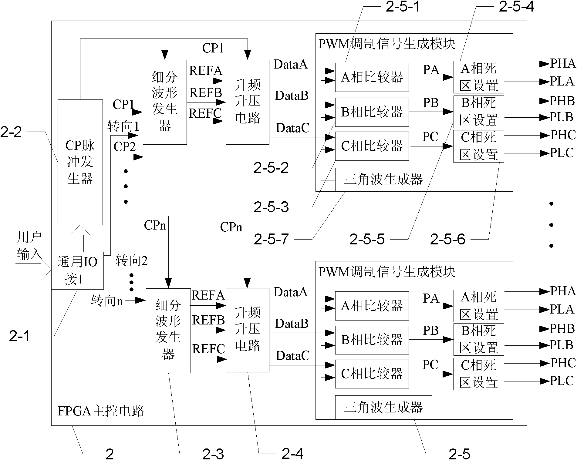
[0049] Specific implementation mode one: the following combination Figure 1 to Figure 11 Describe this embodiment, this embodiment comprises dial switch 1, FPGA main control circuit 2, n road optocoupler isolation circuit 3, n road drive circuit 4, n road three-phase inverter bridge 5, 3n current transformers 6 and n-way overcurrent protection circuit 7,

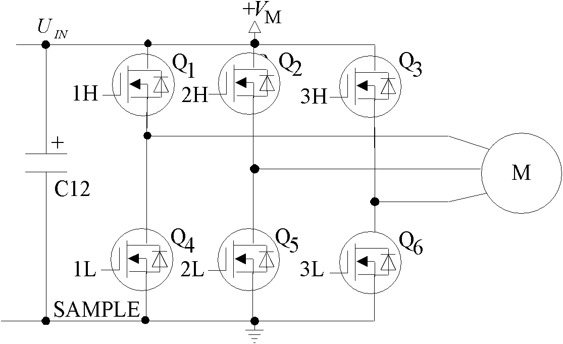
[0050] The output terminal of the dial switch 1 is connected to the input terminal of the FPGA main control circuit 2, and the FPGA main control circuit 2 has n road motor output ports, and each road motor output port is connected to the input end of one road optocoupler isolation circuit 3, and the optocoupler isolation circuit 3 The output terminal of the circuit 3 is connected to the input terminal of the drive circuit 4, the output terminal of the drive circuit 4 is connected to the input terminal of the three-phase inverter bridge 5, and the three output terminals of the three-phase inverter bridge 5 are respectively t...

specific Embodiment approach 2

[0085] Specific implementation mode two: the following combination Figure 12 to Figure 31 Describe this implementation mode, this implementation mode gives specific examples, the experimental object of this system is a three-phase hybrid stepping motor, the model is: 57H370C2500. The base step angle is 1.2° / 0.6°, the phase current is 5.2A, the holding torque is 0.9N·m, and the no-load starting frequency is 2KHz.

[0086] The FPGA main control circuit 2 given in this embodiment provides n=8 motor control signals, but considering the system cost and practicability, only two-way stepper motor isolation drive hardware circuits are made, and only two-way motor drive performance is tested. Related tests, since the FPGA main control circuit 2 provides 8 control signals at the same time, all of them meet the control requirements after testing. Although only two stepper motors are controlled at the same time, it can represent the situation that 8 motors are driven at the same time.

...


PUM


Abstract

The invention relates to a system-on-chip drive of a high-subdivision multi-path stepping motor, belonging to the field of motor control and solving the problems that the traditional stepping motor has the defects of low-frequency oscillation and poor high-frequency output and can not meet the requirement that a plurality of stepping motors work simultaneously and coordinately. The output end of a dial-up switch is connected with the input end of an FPGA main control circuit, the FPGA (Field Programmable Gata Array) main control circuit is provided with n paths of motor output ports, each path of motor output port is connected with the input end of an optical coupler isolation circuit, the output end of the optical coupler isolation circuit is connected with the input end of a drive circuit, the output end of the drive circuit is connected with the input end of a three-phase inversion bridge, three output ends of the three-phase inversion bridge are respectively a three-phase drive current output end of the motor, three current mutual inductors are respectively used for acquiring output currents of three output ends of the three-phase inversion bridge, a phase current signal of the stepping motor, acquired from each current mutual inductor, is output to an overcurrent protection circuit, and the output end of the overcurrent protection circuit is connected with the overcurrent control input end of the drive circuit.

Description

technical field [0001] The invention relates to a system driver on a chip of a high subdivision multi-channel stepping motor, which belongs to the field of motor control. Background technique [0002] The operation of stepper motors cannot be powered by ordinary AC and DC power supplies, and requires special drive equipment, so the performance of stepper motors depends largely on the performance of its drive system. There are a large number of general-purpose stepper motor drivers on the market, which only need to be provided with power supply, direction signal and action pulse signal to work. However, most of them are composed of single-chip microcomputer and discrete components. The system integration is low, the anti-interference ability is poor, and the step angle resolution is not high, resulting in low positioning accuracy of the stepper motor, which restricts the application range of the stepper motor. At the same time, there are also the following defects: [0003]...

Claims


Application Information

Patent Timeline
Patent Type & Authority Applications(China)
IPC IPC(8): H02P8/06H02P8/36H02P8/12H02P8/40
Inventor 杨春玲朱敏李伟亮陈宇张振东
Owner HARBIN INST OF TECH
Learn More