


Quick Research
Generate reliable direction feasibility study reports for your R&D in just a few steps.

Technical Q&A
Discover and master advanced knowledge NOW. Basics, ideas, possibilities, all at once.

Find Solutions
As an expert in R&D theories, this can generate solutions to your technical problems instantly.

Evaluate Feasibility
Analyze your overall solution with one click, know your potential R&D risks in advance.

Monitor Landscape
Get weekly tech updates, stay abreast of the latest tech innovations and key insights.
Optical fiber voltage sensor and adjustment method thereof
A technology of voltage sensor and optical fiber, which is applied in the field of optoelectronics, can solve the problems that the polarization direction of the polarizer and the analyzer cannot be changed accordingly, affect the detection accuracy, and temperature error, so as to overcome the error, reduce the difficulty of adjustment, and the included angle small error effect
- Summary
- Abstract
- Description
- Claims
- Application Information
AI Technical Summary
Problems solved by technology
Method used
Image

Examples
Embodiment 1
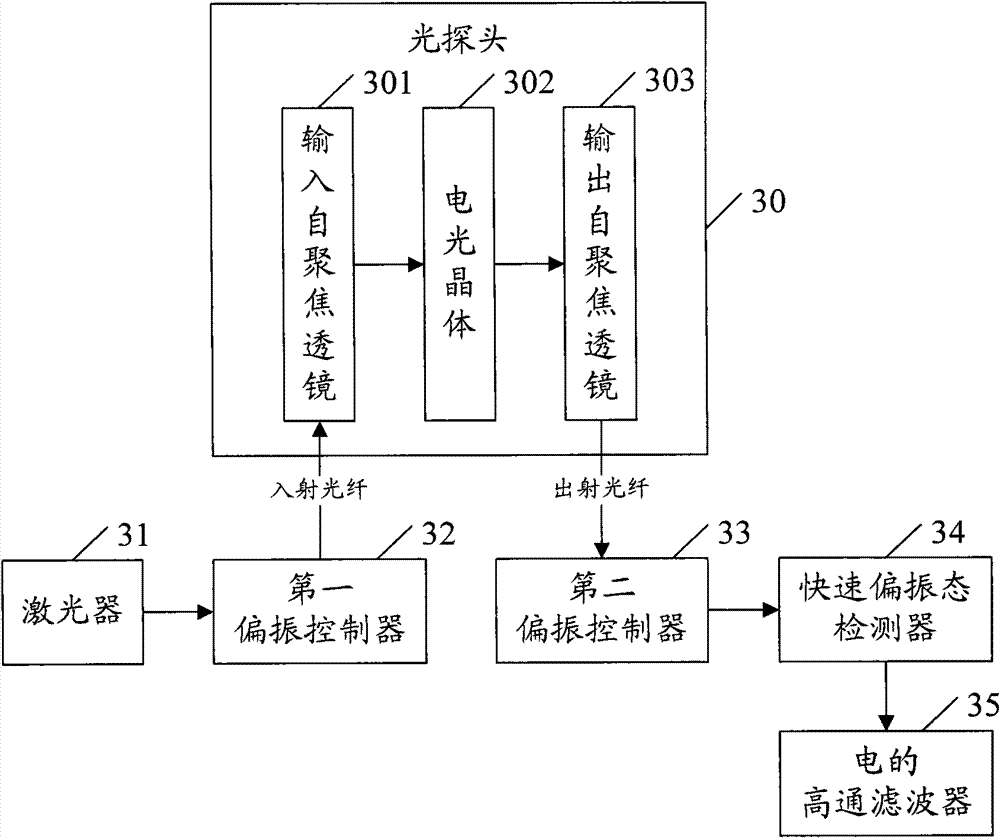
[0033] refer to image 3 , image 3 It is a structural schematic diagram of another embodiment of the fiber optic voltage sensor of the present invention, including a laser 31, a first polarization controller 32, an optical probe 30, a second polarization controller 33, a fast polarization state detector 34 and an electrical high-pass filter 35 . Wherein, the optical probe 30 includes an input self-focusing lens 301 , an electro-optic crystal 302 and an output self-focusing lens 303 .
[0034]Wherein, the first polarization controller 32 is arranged at the input end of the optical probe 30, and the second polarization controller 33 is arranged at the output end of the optical probe 30, that is, the input light reaches the optical probe 30 through the first polarization controller 32 , while the output light reaches the fast polarization state detector 34 through the second polarization controller 33 . The input self-focusing lens 301 receives the input light transmitted thr...
Embodiment 2
[0039] refer to Figure 4 , Figure 4 is a structural schematic diagram of another embodiment of the fiber optic voltage sensor according to the present invention, the sensor includes: a laser 41, a first polarization controller 42, a circulator 43, an optical probe 40, a second polarization controller 44, a fast polarization state detector 45 and electrical high pass filter 46. A laser source 41 emits continuous light.
[0040] In the circulator 43, the first polarization controller 42 is arranged at the first end in the direction of the static bias magnetic field of the circulator, the optical probe 40 is arranged at the second end in the direction of the static bias magnetic field of the circulator 43, and the second polarization The controller 44 is arranged at the third end of the circulator 43 in the direction of the static bias magnetic field. The circulator 43 is a multi-port device that transmits the incident wave entering any port of the port to the next port in s...
Embodiment 3
[0046] refer to Figure 5 , Figure 5 is a structural schematic diagram of another embodiment of the fiber optic voltage sensor according to the present invention, the sensor includes: a laser 51, a first polarization controller 52, a circulator 53, an optical probe 50, a second polarization controller 54, a fast polarization state detector 55 and electrical high pass filter 56. The laser source 51 emits pulsed light.
[0047] In the circulator 53, the first polarization controller 52 is arranged at the first end in the direction of the static bias magnetic field of the circulator, the optical probe 50 is arranged at the second end in the direction of the static bias magnetic field of the circulator 53, and the second polarization The controller 54 is disposed at the third end of the circulator 53 in the direction of the static bias magnetic field. The circulator 53 is a multi-port device that transmits the incident wave entering any port to the next port in sequence accord...
PUM
 Abstract
Description
Claims
Application Information
 - R&D Engineer
- R&D Manager
- IP Professional
- Industry Leading Data Capabilities
- Powerful AI technology
- Patent DNA Extraction
Browse by: Latest US Patents, China's latest patents, Technical Efficacy Thesaurus, Application Domain, Technology Topic, Popular Technical Reports.
© 2024 PatSnap. All rights reserved.Legal|Privacy policy|Modern Slavery Act Transparency Statement|Sitemap|About US| Contact US: help@patsnap.com