
Vacuum vibration forming device for manufacturing artificial stones

A technology of vibration molding and artificial stone, which is applied in the direction of manufacturing tools and ceramic molding machines, which can solve the problems of difficult demoulding, uneven appearance, and low production cost, so as to prevent the generation of air holes and the sinking of solidified particles, and achieve good results. The effect of aesthetic appearance, high hardness and wear resistance

Active Publication Date: 2011-02-09
GUANGDONG FUSHENG INNOVATIVE MATERIAL TECH LTD
View PDF0 Cites 7 Cited by
  • Summary
  • Abstract
  • Description
  • Claims
  • Application Information

AI Technical Summary

Problems solved by technology

[0002] The production of existing artificial stone mostly uses stone powder and synthetic resin as raw materials, and is a kind of artificial building decoration material formed by solidification in the mold cavity. At present, there are two main production methods of artificial stone. One is manual production. Although the equipment used is relatively simple and the labor intensity is relatively high, the production cost is relatively low because the resin content used is only about 28%. The second is mechanized automatic pouring production. Higher, but the resin content is as high as 33%, so its production cost is higher
In addition, when using mechanized production, because the curing agent used is very corrosive, it needs to be shut down for cleaning every two hours, which makes it impossible to achieve large-scale and high-efficiency production. More importantly, during the curing process In the process, due to the sinking of resin particles and the precipitation of low-molecular liquid, the volume of artificial stone will shrink, the surface will wrinkle and the defects of porosity will lead to uneven overall strength of the product, uneven appearance and difficulty in demoulding.

Method used


Image

  • Vacuum vibration forming device for manufacturing artificial stones
  • Vacuum vibration forming device for manufacturing artificial stones
  • Vacuum vibration forming device for manufacturing artificial stones

Examples


Embodiment Construction

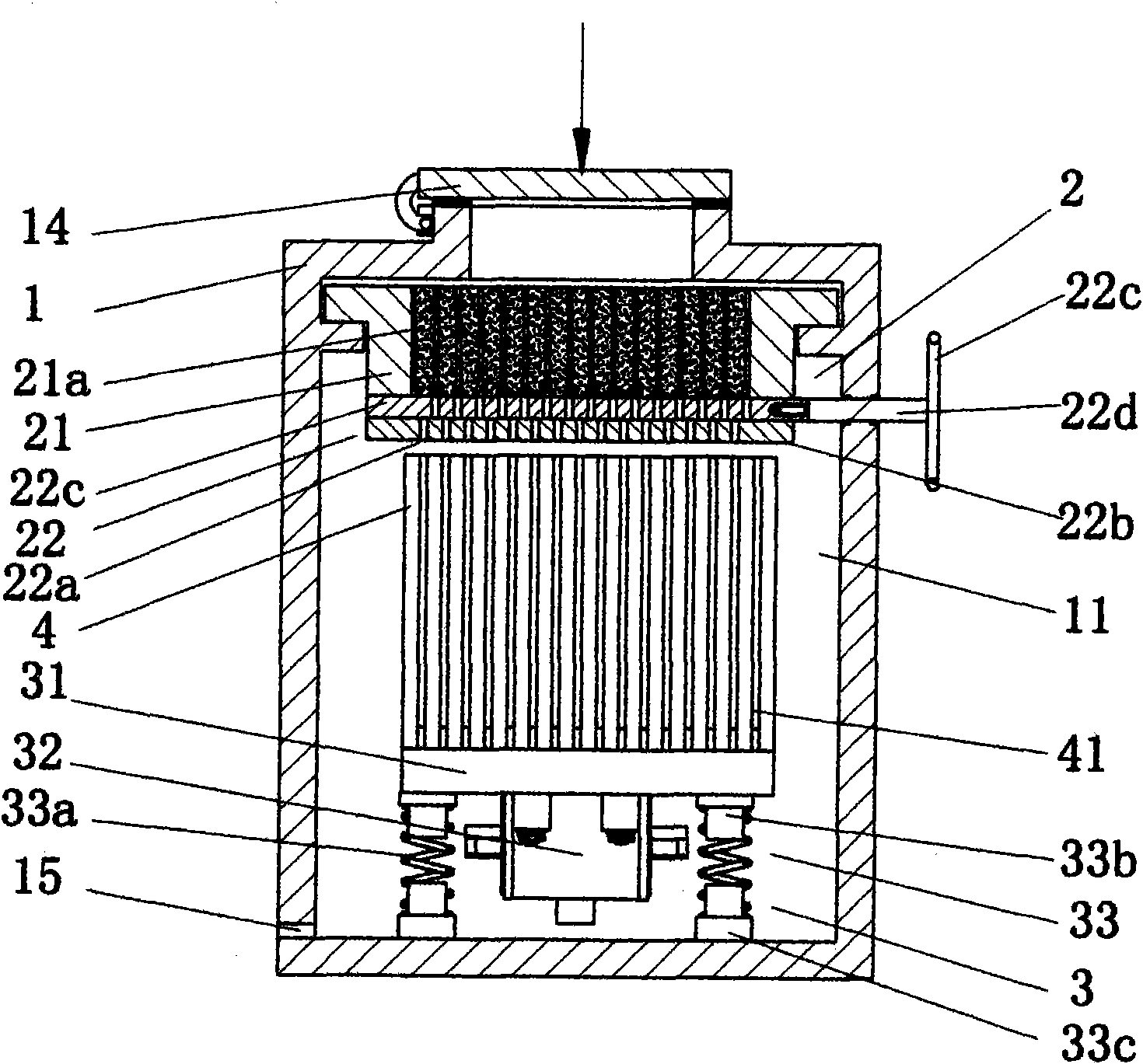
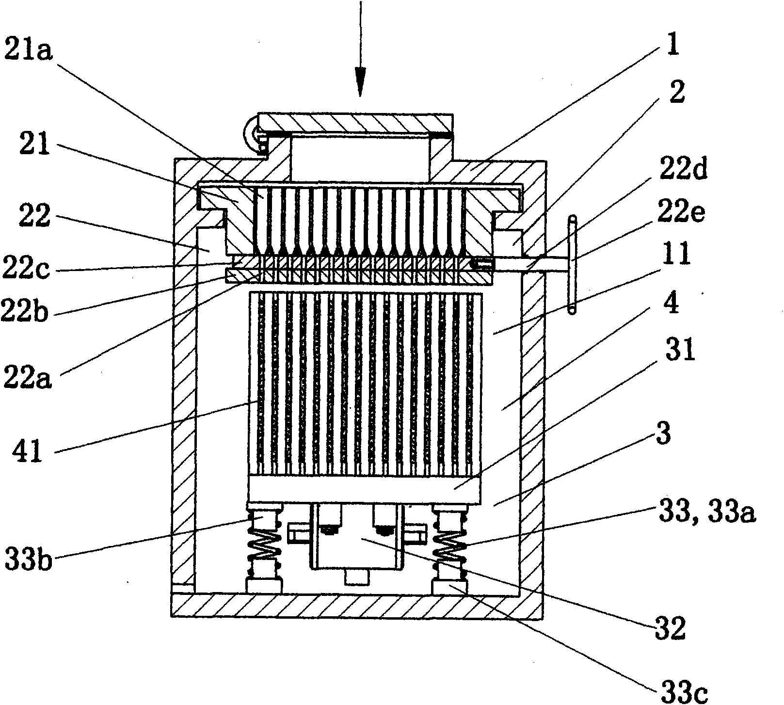
[0010] The present invention as figure 1 , figure 2 , image 3 As shown, a vacuum vibration forming device for making artificial stones comprises a box body 1, the sides of the box body 1 are provided with box doors, and the top of the box body 1 is provided with a feed port, and the box body 1 is provided with A vacuumized inner cavity 11 is provided with a filling device 2 above the inner cavity 11 near the feeding port, a vibrating table 3 is provided on the bottom surface of the inner cavity 11, and a mold 4 is arranged on the vibrating table 3 .

[0011] Above-mentioned packing device 2 comprises hopper 21, discharge plate 22, is provided with the hopper 21a that some use material plate to separate in the bucket cavity of this hopper 21, is provided with the plate surface that can correspond to each chute 21a in this discharge plate 22. Adjust the opening or closing of the discharge port 22a; the above-mentioned mold 4 is provided with mold cavities 41 arranged vertica...


PUM


Abstract

The invention discloses a vacuum vibration forming device for manufacturing artificial stones. The device comprises a box body, wherein box doors are arranged on two sides of the box body; a feed inlet is reserved at the top of the box body; the box body is provided with a vacuumized inner cavity; a packing device is arranged on the upper part, close to the feed inlet, of the inner cavity; a vibration bench is arranged on the bottom face of the inner cavity; and a die is arranged on the inner vibration bench. Due to the adoption of the structure that the packing device and the vibration benchare arranged in the vacuumized inner cavity and the die is arranged on the inner vibration bench, the generation of air holes in stone materials and the subsidence of cured particles are effectively prevented through vacuuming and vibration in a curing and forming process that the mixed stone materials enter the packing device and the die from the feed inlet. The manufactured stone materials haverelatively high rigidity, wear resistance and attractive appearance.

Description

technical field [0001] The invention relates to an artificial stone production equipment, in particular to a vacuum vibration forming device for artificial stone production. Background technique [0002] The production of existing artificial stone mostly uses stone powder and synthetic resin as raw materials, and is a kind of artificial building decoration material formed by solidification in the mold cavity. At present, there are two main production methods of artificial stone. One is manual production. Although the equipment used is relatively simple and the labor intensity is relatively high, the production cost is relatively low because the resin content used is only about 28%. The second is mechanized automatic pouring production. Higher, but the resin content is as high as 33%, so its production cost is higher. In addition, when using mechanized production, because the curing agent used is very corrosive, it needs to be shut down for cleaning every two hours, which ma...

Claims


Application Information

Patent Timeline
IPC IPC(8): B28B1/087
Inventor 龚学锋
Owner GUANGDONG FUSHENG INNOVATIVE MATERIAL TECH LTD
Learn More