
Smooth heat exchanger of sewage or surface water source heat pump and system thereof

A technology of surface water source heat pump and heat exchange device, applied in the energy field, can solve the problems of complex process flow, large land occupation, blockage of suspended matter, etc., and achieve the effects of high heat exchange efficiency, reduced cleaning workload, and small flow resistance.

Inactive Publication Date: 2011-01-12
青岛科创蓝新能源股份有限公司
View PDF6 Cites 10 Cited by
  • Summary
  • Abstract
  • Description
  • Claims
  • Application Information

AI Technical Summary

Problems solved by technology

[0011] The purpose of the present invention is to provide a sewage or surface water source heat pump unimpeded heat exchange device and its system, which can effectively solve the blockage of suspended solids and the complex process flow and large area occupation caused by the existing technology to prevent blockage. The key issue

Method used


Image

  • Smooth heat exchanger of sewage or surface water source heat pump and system thereof
  • Smooth heat exchanger of sewage or surface water source heat pump and system thereof
  • Smooth heat exchanger of sewage or surface water source heat pump and system thereof

Examples


specific Embodiment approach 1

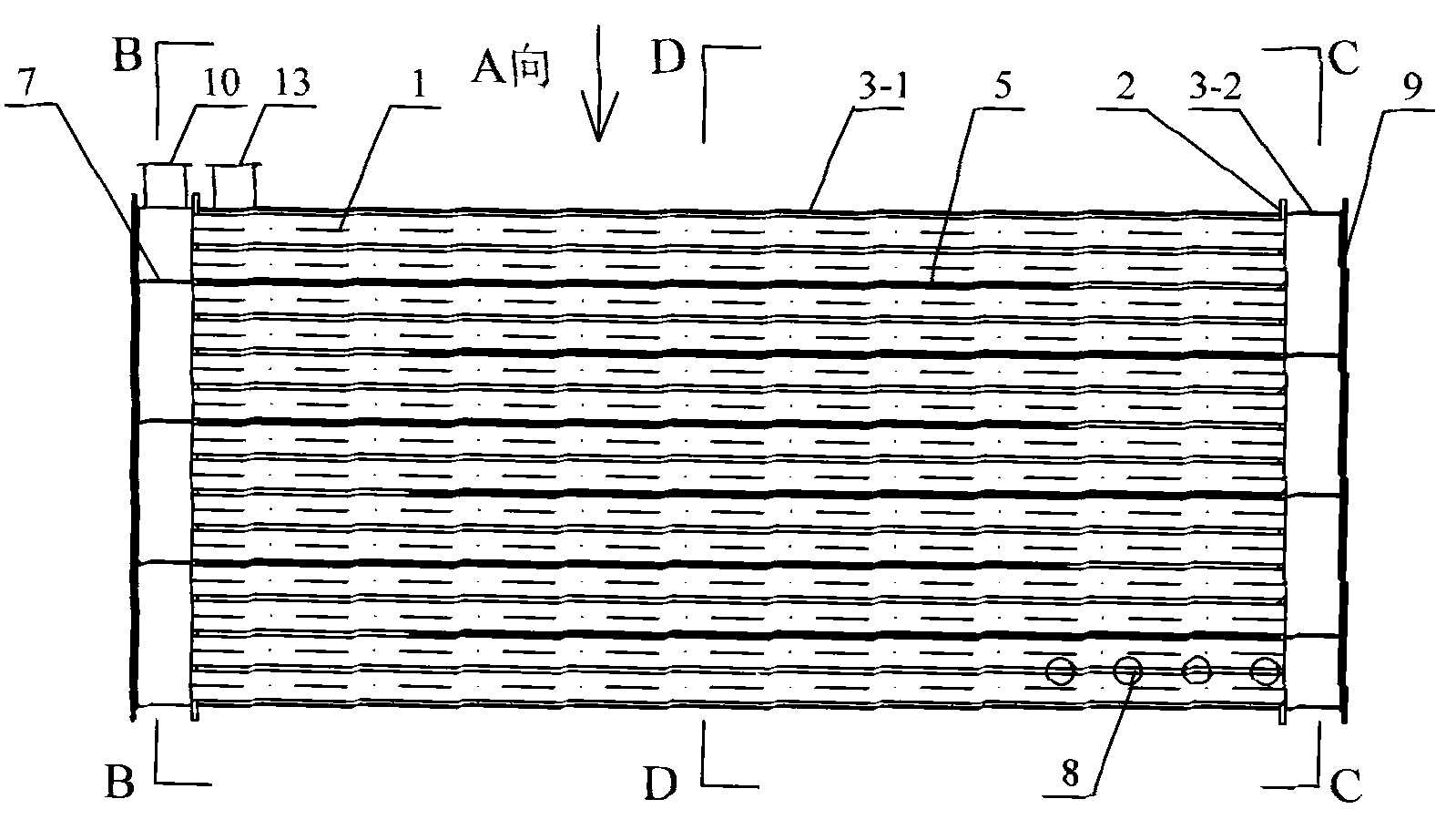
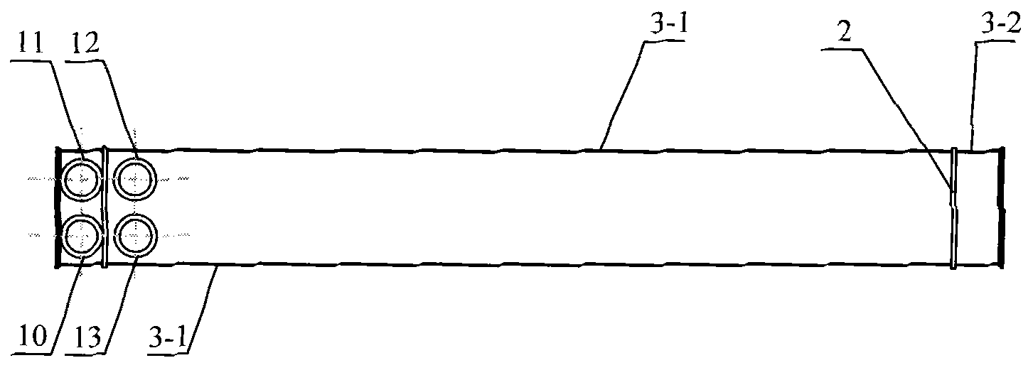
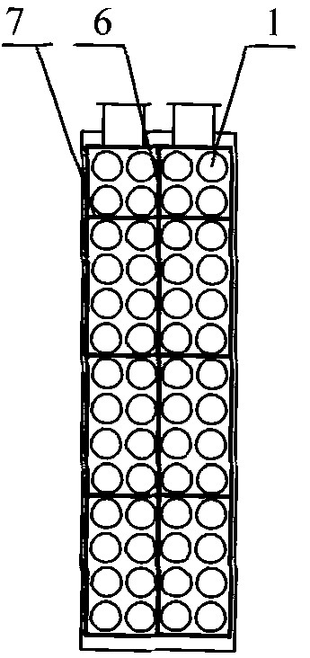
[0030] Specific implementation mode one, combining figure 1 , figure 2 , image 3 , Figure 4 , Figure 5 Be explained. The unimpeded heat exchange device of this embodiment consists of a large diameter tube 1, a tube plate 2, a shell 3-1, a shell 3-2, an inner longitudinal diaphragm 4, an inner transverse diaphragm 5, an outer longitudinal diaphragm 6, an outer Diaphragm 7, bypass hole 8, sealing plate 9, sewage or surface water inlet 10, sewage or surface water outlet 11, clean water inlet 12, clean water outlet 13, the large diameter tube 1 is fixed on the tube plate 2; shell The bodies 3-1 and 3-2 are respectively connected with the tube sheet 2; the inner longitudinal diaphragm 4 is fixed on the tube sheet 2 and the shell 3-1, and divides the interior of the shell 3-1 into two parts; one end of the inner diaphragm 5 is connected with The tube plate is connected, and the other end is left with a certain water passing distance with the other tube plate 2, and the two ...

specific Embodiment approach 2

[0031] Specific implementation mode two (see Figure 1 to Figure 5 ), the diameter of the large-diameter pipe 1 of this embodiment is 70-125 mm, and other components and connections are the same as those in Embodiment 1.

specific Embodiment approach 3

[0032] Specific implementation mode three (see Figure 1 to Figure 5 ), the diameter of the large-diameter pipe 1 of this embodiment is 90-110mm, and other compositions and connections are the same as those in Embodiment 1.


PUM


Abstract

The invention relates to a smooth heat exchanger of sewage or a surface water source heat pump and a system thereof, in particular to a heat exchanger for extracting heat or cold from the sewage or surface water by using a heat pump technology and a system thereof, belonging to the technical field of energies. The invention aims to solve the key problems of suspended matter blocking, and complex technical process, great floor area and the like which are caused by trying to realize blocking prevention in the prior art. The heat exchanger is composed of a large-diameter pipe, a pipe sheet, a shell, inner and outer partitions, closing plates, sewage or surface water inlet and outlet, clear water inlet and outlet and the like. The system is composed of the heat exchanger, a heat pump set, a water pump, connecting pipelines and the like. The sewage or the surface water can smoothly flow in the large-diameter pipe, the clear water and the sewage form countercurrent flow in the shell, and the heat pump set extracts heat from the clear water. The invention is suitable for a sewage or surface water source heat pump indirect system, and the front end does not need a filter screen or an anti-blocking device, thereby realizing continuous heat exchange and heat extraction without blocking. The invention has the advantages of simplified system and technical process, high heat exchange efficiency and small floor area.

Description

technical field [0001] The invention relates to a heat exchange device and system for extracting heat or cold from sewage or surface water by using heat pump technology, and belongs to the field of energy technology. Background technique [0002] The use of heat pump technology to extract low-level thermal energy from sewage or surface water for building heating and air conditioning, that is, sewage or surface water source heat pump heating and air conditioning systems, has huge energy-saving potential, and its energy-saving rate can reach more than 45%. According to the calculation and calculation of the existing sewage discharge in our country, the development and utilization of low-level thermal energy of sewage (according to the temperature drop of 4-5°C) can provide heating and air conditioning for 20% of urban buildings. one of the ways. [0003] Sewage source or surface water source is a kind of water source. Compared with groundwater, its main feature is that the co...

Claims


Application Information

Patent Timeline
Patent Type & Authority Applications(China)
IPC IPC(8): F28D7/16F28F9/02F28F9/22F25B30/06
CPCY02B30/52Y02B30/123
Inventor 吴荣华迟芳
Owner 青岛科创蓝新能源股份有限公司
Learn More