Energy-saving radiant tube component

A technology of radiant tubes and components, which is applied in the field of energy-saving radiant tube components, can solve the problems of low energy utilization rate and high flue gas temperature, and achieve the effects of improving energy utilization rate, high combustion temperature, and reducing exhaust gas temperature

Inactive Publication Date: 2011-01-12
BEIJING JJRS TECH DEV
View PDF9 Cites 7 Cited by
  • Summary
  • Abstract
  • Description
  • Claims
  • Application Information

AI Technical Summary

Problems solved by technology

[0005] An embodiment of the present invention provides an energy-saving radiant tube assembly, which is used to solve the problems in the prior art that the temperature of the flue gas discharged from the radiant tube is high and the energy utilization rate is low

Method used


Image

  • Energy-saving radiant tube component
  • Energy-saving radiant tube component
  • Energy-saving radiant tube component

Examples


Embodiment 1

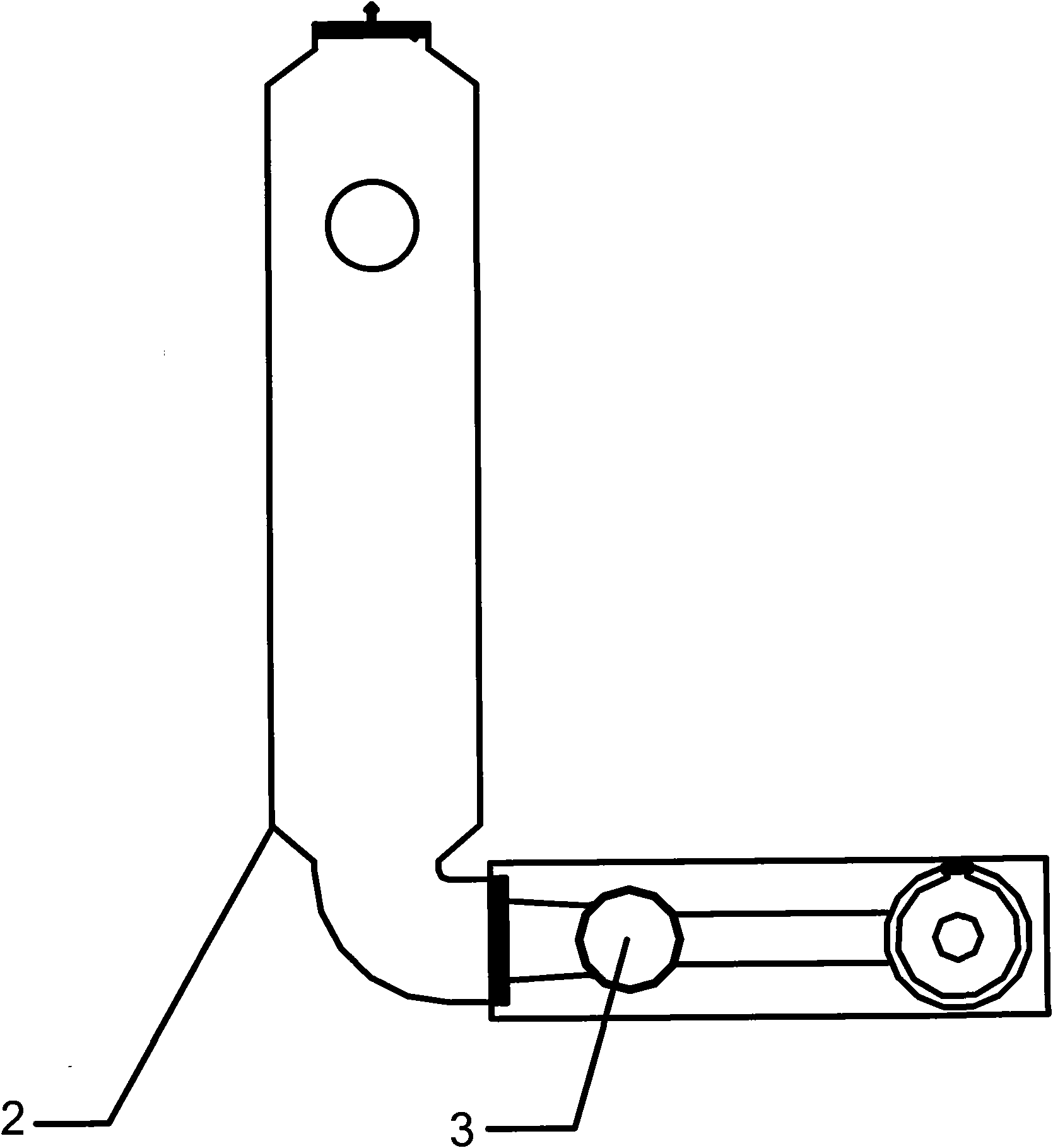
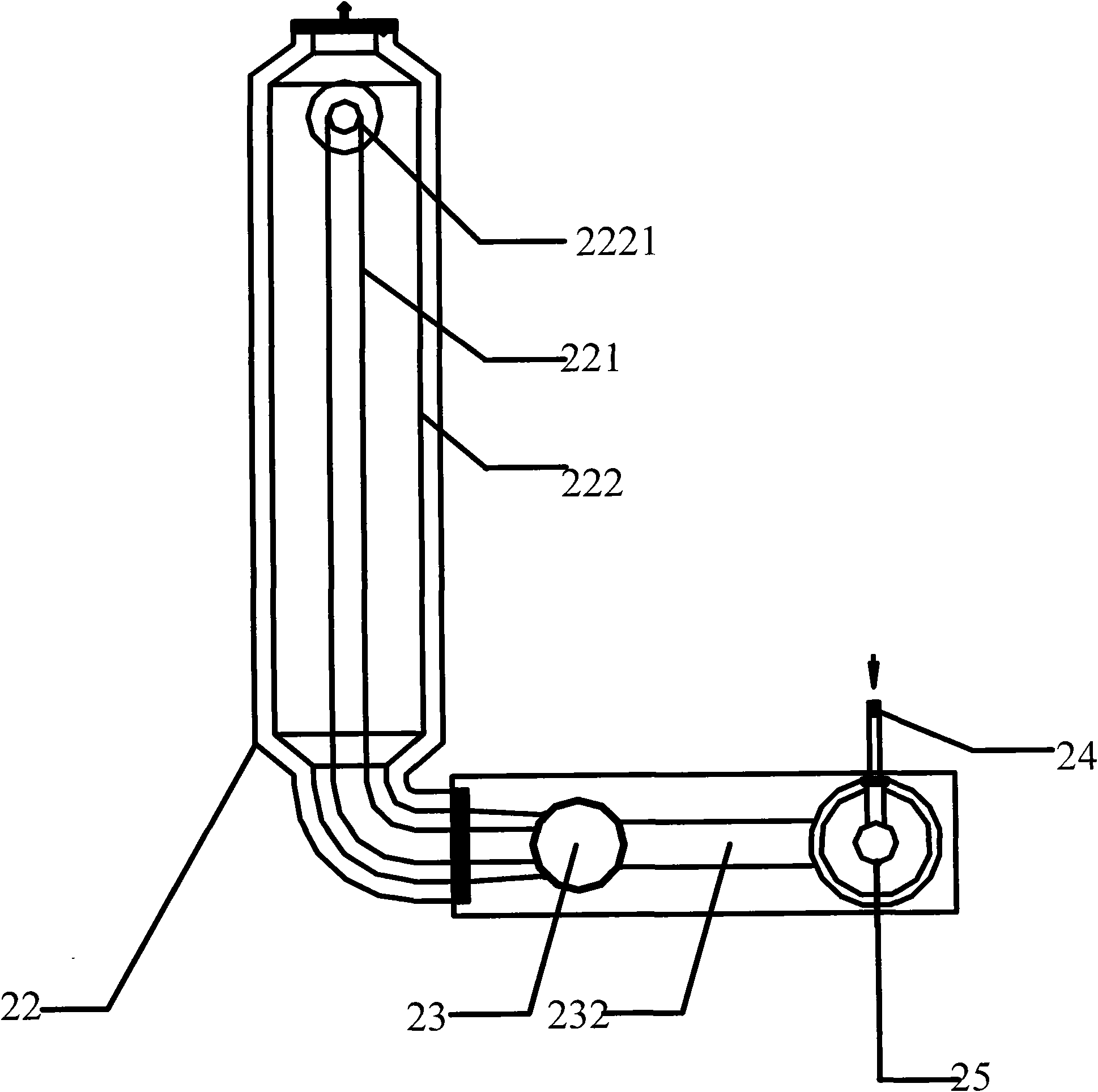
[0047] Such as Figure 2A-2B As shown, an energy-saving radiant tube assembly provided by an embodiment of the present invention includes a radiant tube 21, a primary heat exchanger 22 and a secondary heat exchanger 23, wherein:

[0048] The primary heat exchanger 22 includes: double-layer tubes, including inner tubes and outer tubes, wherein:

[0049] The outer tube is a first air tube 222, which has a first air inlet and a first air outlet for introducing air;

[0050] The inner pipe is the first flue gas pipe 221, which has a first flue gas inlet and a first flue gas outlet, and is used to receive and discharge the flue gas introduced by the secondary heat exchanger 23, and use the heat of the flue gas to guide the first flue gas. The air in the air pipe 222 is preheated for the first time;

[0051] The first air pipe 222 is also used to lead the first preheated air to the secondary heat exchanger 23 .

[0052] The secondary heat exchanger 23 includes a second flue gas p...

Embodiment 2

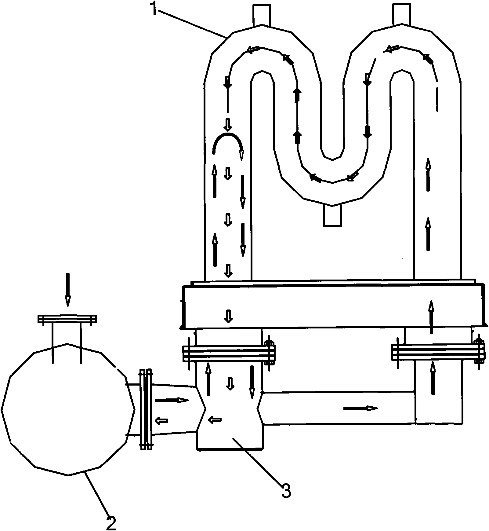
[0064] Such as Figure 3A-3B As shown, another energy-saving radiant tube assembly provided by the embodiment of the utility model includes a radiant tube 31, a primary heat exchanger 32 and a secondary heat exchanger 33, wherein:

[0065] The primary heat exchanger 32 includes: a double-layer tube, including an inner tube and an outer tube, wherein:

[0066] The inner tube is a first air tube 322, which has a first air inlet and a first air outlet, and is used to introduce air;

[0067] The outer pipe is the first flue gas pipe 321, which has a first flue gas inlet and a first flue gas outlet, and is used to receive and discharge the flue gas introduced by the secondary heat exchanger 33, and use the heat of the flue gas to guide the first flue gas. The air in the air pipe 322 is preheated for the first time;

[0068] The first air pipe 322 is also used to lead the first preheated air to the secondary heat exchanger 33 .

[0069] The secondary heat exchanger 33 includes a ...


PUM


Abstract

The invention provides an energy-saving radiant tube component which is used for solving the problems of high temperature of flue gas exhausted from a radiant tube and low utilization rate of energy in the prior art. The energy-saving radiant tube component comprises the radiant tube, as well as a primary heat exchanger and a secondary heat exchanger, wherein the primary heater exchanger is used for receiving and exhausting the flue gas led-in by the secondary heat exchanger, leading-in air, utilizing the energy of the flue gas to carry out first preheating on the air and leading-out the air after the first preheating to the secondary heat exchanger, wherein the flue gas is exhausted by the radiant tube; and the secondary heat exchanger is used for leading-in the flue gas into the primary heat exchanger, receiving the air after the first preheating, utilizing heat of the flue gas to carry out second preheating on the air after the first preheating, and leading-out the air after the second preheating to a burner combustion-supporting air inlet of the radiant tube. The technical scheme can reduce the temperature of exhaust smoke and improve the utilization rate of the energy and the heating efficiency of the radiant tube.

Description

technical field [0001] The invention relates to the technical field of industrial furnaces, in particular to an energy-saving radiant tube assembly. Background technique [0002] Radiant tube heating is usually used in metallurgical strip continuous annealing production lines, hot-dip galvanizing, hot-dip aluminum, hot-dip galvanized silicon production lines and other occasions that need to be isolated from gas for heating. Gas (that is, gas fuel) burns in the radiant tube and radiates through the tube wall to indirectly heat the product. [0003] The existing radiant tubes can be divided into straight single tubes, U-shaped tubes and W-shaped tubes. The types of radiant tubes can be divided into non-recirculating radiant tubes and recirculating radiant tubes. Except for non-recirculating single-ended radiant tubes, other non-recirculating radiant tubes are usually provided with a burner at one end and a flue gas outlet at the other end. The existing technology uses the f...

Claims


Application Information

Patent Timeline
Patent Type & Authority Applications(China)
IPC IPC(8): F23D14/12F23D14/66
CPCY02E20/34
Inventor 许雷
Owner BEIJING JJRS TECH DEV
Why Eureka
Try Eureka