Torsion bar type automobile suspension device
A suspension device and torsion bar type technology, applied in the direction of control devices, suspensions, elastic suspensions, etc., can solve the problems of uncomfortable passengers, easy deformation of the frame and body frame, damage to goods, etc., and achieve good vibration reduction effect Effect
- Summary
- Abstract
- Description
- Claims
- Application Information
AI Technical Summary
Problems solved by technology
Method used
Image

Examples
Embodiment 1
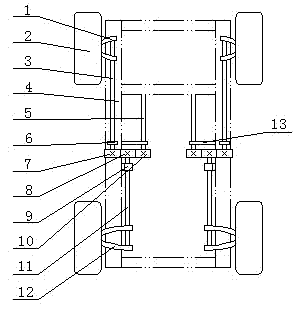
[0026] like figure 1 As shown, the upper end of the front torsion bar spring 3 is connected with the control arm 1 of the front suspension of the automobile, the control arm of the front suspension is connected with the wheel 2, and the lower end of the rear torsion bar spring 11 is connected with the control arm 12 of the rear suspension. The lower end of the front torsion bar spring of the side and the right side and the upper end of the rear torsion bar spring are equipped with gears 7,8 respectively, and two pairs of gears on the front and rear torsion bar springs of the above-mentioned same side mesh with each other. The upper ends of the two reset torsion bar springs 5 are fixedly connected with the vehicle frame 4, and the lower ends are equipped with a reset gear 10, which meshes with the gear 8 on the rear torsion bar spring on the same side. Rod spring links to each other with vehicle frame by front torsion bar spring bearing seat 6, rear torsion bar spring bearing...
Embodiment 2
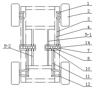
[0030] On the basis of the structure of Embodiment 1, in order to prevent the intermeshed gears from being polluted by various impurities and affecting their service life, as figure 2 As shown, three gears meshing with each other on the same side are placed in the gearbox 14, on the one hand, the working conditions of the gears are changed, on the other hand, after the gearbox 14 is fixed on the vehicle frame 4, the three torsion bar springs on the same side Through the positioning of the gearbox, the mutual meshing of the three gears can be ensured, and three pairs of bearing seats are omitted. Simultaneously in order to make front and rear torsion bar spring recover deformation rapidly after torsion deformation, two resetting torsion bar springs are installed, i.e. front resetting torsion bar spring 5-1 and rear resetting torsion bar spring 5-2.
Embodiment 3
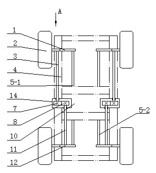
[0032] On the structural basis of Embodiment 2, when the control arms of the front and rear suspensions are double-wishbone structures, as image 3 , 4As shown, the upper ends of the front torsion bar springs 3 on the left and right sides are installed on the upper cross arms 1-1 of the front suspension control arms 1 on the left and right sides, and the lower ends of the rear torsion bar springs 11 on the left and right sides are installed on the left and right sides On the upper cross arm of the rear suspension control arm 12, the reset torsion bar spring 5 is made up of two front reset torsion bar springs 5-1 and two rear reset torsion bar springs 5-2, and the front reset torsion bar spring 5-1 The upper end links to each other with the lower cross arm 1-2 of the double wishbone of the control arm 1 of the front suspension, and the rear reset torsion bar spring 5-2 lower end links to each other with the lower cross arm of the rear suspension control arm 12, and the front re...
PUM
 Abstract
Description
Claims
Application Information
 - R&D
- Intellectual Property
- Life Sciences
- Materials
- Tech Scout
- Unparalleled Data Quality
- Higher Quality Content
- 60% Fewer Hallucinations
Browse by: Latest US Patents, China's latest patents, Technical Efficacy Thesaurus, Application Domain, Technology Topic, Popular Technical Reports.
© 2025 PatSnap. All rights reserved.Legal|Privacy policy|Modern Slavery Act Transparency Statement|Sitemap|About US| Contact US: help@patsnap.com