
Ultrasonic pulse resonance jet rotary spray-head device

A technology of jet rotation and pulse jet, which is applied in the direction of injection devices, liquid injection devices, chemical instruments and methods, etc., and can solve the problems of low cleaning efficiency of single-nozzle vortex nozzles, inability to form pulsed oscillating jets, poor impact force and cleaning effect, etc. , to achieve the effects of improving striking force and cleaning efficiency, long life, and increasing cleaning width and area

Inactive Publication Date: 2012-04-18
西安远诚机电科技有限公司
View PDF2 Cites 0 Cited by
  • Summary
  • Abstract
  • Description
  • Claims
  • Application Information

AI Technical Summary

Problems solved by technology

[0006] 1. The cleaning effect of the existing single-nozzle vortex nozzle is better, which can increase the impact force and cleaning effect by about 5-7 times. However, due to its narrow cleaning width and small cleaning area, the cleaning efficiency of the single-nozzle vortex nozzle lower;
[0007] 2. Although the existing pulse jet rotary nozzle has improved its cleaning width and area, due to the defect of the mixing chamber structure of its pulse jet, the nozzle outlet is far away from the multi-head horn, and the ultrasonic attenuation energy loss is large, which cannot form a stable The pulse oscillating jet has poor striking force and cleaning effect, and the cleaning efficiency is still low

Method used


Image

  • Ultrasonic pulse resonance jet rotary spray-head device
  • Ultrasonic pulse resonance jet rotary spray-head device
  • Ultrasonic pulse resonance jet rotary spray-head device

Examples


Embodiment Construction

[0022] The specific embodiments of the present invention will be further described below in conjunction with the accompanying drawings.

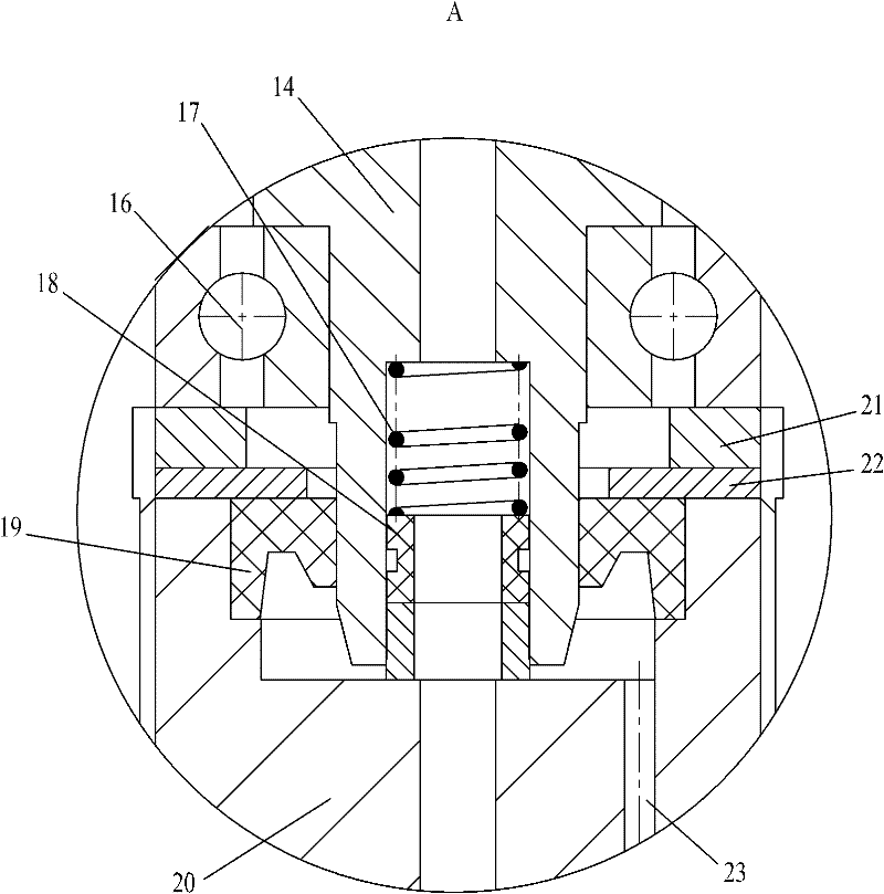
[0023] figure 1 , figure 2 Including nozzle seat 1, nozzle 2, multi-head horn 3, nozzle housing 4, oscillation chamber 5, pulse jet inlet 6, ultrasonic transducer body 7, piezoelectric ceramic sheet 8, high-pressure rotary sealing device 9, rotary Device 10, transducer shield 11, rotating brush 12, ultrasonic signal input cable 13, transducer central shaft 14, micro luffing head 15, lower bearing 16, self-tightening spring 17, sealing packing 18, oil seal 19, Rotating body 20, upper washer 21, lower washer 22, rotating body discharge hole 23, pressing device 24, upper bearing 25, high-pressure water channel 26, transducer body draining hole 27, double-ended stud 28, cavity 29, Central through hole 30, copper pad 31, etc.

[0024] Such as figure 1 As shown, the present invention is an ultrasonic pulse resonance jet rotary nozzle device, ...


PUM


Abstract

The invention relates to an ultrasonic pulse resonance jet rotary spray-head device which comprises an ultrasonic transducer and a spray head, wherein a longitudinal pulse jet inlet is drilled in an ultrasonic transducer body, the ultrasonic transducer body is rotatably installed on the central shaft of the transducer, a high-pressure rotary sealing device is arranged between the central shaft ofthe transducer and the ultrasonic transducer body, an axial high-pressure water channel communicated with the longitudinal pulse jet inlet is drilled in the central shaft of the transducer, and an ultrasonic transduction vibrator is arranged outside the central shaft of the transducer; and an oscillation cavity is arranged in the shell of the spray head, a plurality of nozzles are arranged at thelower end of the shell of the spray head, a multi-head amplitude-changing rod is arranged in the oscillation cavity, and a plurality of miniature amplitude-changing heads are fixedly connected onto the multi-head amplitude-changing rod. The design of the rotary ultrasonic transducer and the spray head is adopted by the invention, the oscillation cavity is arranged in the shell of the spray head, and the multi-head amplitude-changing rod is arranged in the oscillation cavity, thereby improving the energy conversion efficiency, increasing the cleaning width and area of the ultrasonic pulse resonance jet rotary spray-head device and greatly improving the cleaning efficiency of the ultrasonic pulse resonance jet rotary spray-head device.

Description

technical field [0001] The invention relates to an ultrasonic pulse resonant jet device for industrial cleaning, surface coating stripping, deburring, rust removal, paint removal or steel surface descaling by using ultrasonic oscillating pulse jet, specifically an ultrasonic pulse resonant jet rotary nozzle device . Background technique [0002] High-pressure water jet technology and equipment is a high-tech developed in the 1970s and widely used in industrial cleaning, cutting, deburring, surface coating peeling, rust and paint removal, etc. After decades of rapid development, several major fields such as pure water jet, abrasive water jet, unsteady water jet and ultrasonic water jet have been formed. In general industrial cleaning, most of them use continuous high-pressure pure water jets. In the fields of rust removal, paint removal and surface coating peeling, the pressure of high-pressure water required by pure water high-pressure water jets is generally 150~250Mpa, w...

Claims


Application Information

Patent Timeline
Patent Type & Authority Patents(China)
IPC IPC(8): B05B17/06B08B3/12B08B3/02
Inventor 任保林徐合刚叶乔
Owner 西安远诚机电科技有限公司
Learn More